

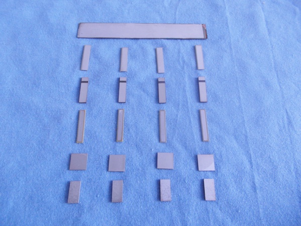
When high power piezoelectric ceramic components run continuously, failure rarely comes from one dramatic event. In most field cases, the real cause is accumulated stress: heat that never fully dissipates, vibration that slowly shifts the assembly out of its safe operating condition, electrical drive that looks acceptable on paper but becomes destructive under real load, or mounting conditions that turn a robust transducer into a fragile one. For maintenance teams, this matters because the failed ceramic itself is often only the last visible symptom. The root problem may sit in the driver, the horn, the preload, the cooling path, or the process duty cycle.
That is why replacing the ceramic stack without diagnosing operating conditions often leads to repeat failures. In continuous-load systems such as ultrasonic welding, cleaning, drilling, flow measurement, sonar, or industrial sensing, the service life of piezo parts depends less on nominal specification and more on how the whole electromechanical system behaves over time.
Failure under continuous load is usually a system problem, not only a material problem
In after-sales service, it is common to hear that a ceramic “burned out” or “cracked for no reason.” In reality, high power piezoelectric ceramic components fail because the ceramic is the most sensitive part of an energy conversion chain. It converts electrical energy into mechanical motion, and any mismatch in that chain shows up quickly in the ceramic as excess temperature, depolarization, mechanical fatigue, dielectric loss, or fracture.
A useful field mindset is this: if the same model of component works reliably in one machine but fails early in another, the investigation should start with operating conditions rather than assuming a bad batch. Manufacturing defects do exist, but repeated service failures are more often linked to resonance drift, unstable clamping force, poor heat dissipation, overvoltage, or off-design loading.
Heat is the most common hidden driver of failure
Continuous operation creates a thermal reality that short-cycle testing often misses. A piezoelectric ceramic may perform well during startup, during a bench test, or even for several minutes under nominal load. Problems emerge when internal losses generate more heat than the assembly can remove.
The heat sources are usually combined:
- dielectric loss inside the ceramic under high electric field,
- mechanical loss from repeated stress cycles,
- frictional loss at interfaces,
- heating in bolts, electrodes, horns, backing masses, and matching structures,
- reflected energy caused by load mismatch.
Once temperature rises, several things can happen at the same time. Resonance shifts, impedance changes, bonding layers soften, preload relaxes, and the ceramic’s electromechanical performance drops. In severe cases, partial depolarization begins. If the operating temperature approaches the material’s safe working limit, the damage may be progressive and not immediately visible. A transducer can still run, but with lower amplitude, unstable current draw, and rising power demand until final failure occurs.
For maintenance personnel, a key mistake is judging health only by whether the unit still vibrates. A transducer that still produces output may already be in thermal decline. Tracking temperature rise during stabilized operation is often more informative than a cold resistance or capacitance check.
Depolarization is often misdiagnosed as simple aging
Piezoelectric ceramics depend on stable polarization. Under continuous load, excessive temperature, excessive electric field, or combined thermo-mechanical stress can disturb that polarization. The result is reduced coupling efficiency, lower displacement, and increasing instability.
In the field, depolarization is often mistaken for normal wear because the change may be gradual. Operators may compensate by increasing drive voltage or extending run time. That temporarily restores output but accelerates the underlying damage. By the time the unit comes to after-sales service, the ceramic may show weak response, abnormal impedance behavior, and elevated self-heating even at moderate drive levels.
This is one reason maintenance records should include not only failure date but also any history of power increases, tuning adjustments, or process changes. Many ceramic failures are preceded by “small” operating corrections made to keep production running.
Mechanical overload does not always mean obvious impact or breakage
Cracked ceramics are easy to identify, but the cause is not always a single overload event. In high power assemblies, the ceramic sees alternating compressive and tensile stress. Even when the design keeps the stack mostly under compression, poor assembly conditions can introduce bending, stress concentration, or uneven pressure distribution.
Common field causes include:
- incorrect bolt torque or preload loss after thermal cycling,
- misalignment between the ceramic stack and front/back masses,
- surface flatness problems at contact interfaces,
- horn or tool wear that changes the load path,
- side loading during installation,
- running the transducer against an unexpected process resistance.
Under continuous load, even a slight bending moment can become destructive because ceramics tolerate compression far better than tensile or shear stress. A stack may survive intermittent use but fail rapidly in 24/7 service where the stress cycle count rises dramatically.
When a ceramic ring breaks, the fracture pattern can be instructive. Clean radial cracking may suggest mechanical overstress or uneven preload. Chipping near contact edges can point to assembly damage or stress concentration. Darkened areas, electrode damage, or signs of local heating may indicate that electrical and thermal causes contributed before the fracture occurred.
Running off resonance is one of the fastest ways to shorten service life
Many high power piezoelectric ceramic components are designed to operate near a specific resonance. In real applications, resonance is not fixed. It shifts with temperature, mounting condition, process contact, tool wear, and aging of adjacent mechanical parts.
If the drive system does not track resonance well, or if the control window is too broad, the transducer may continue operating while drawing higher current and converting less of that energy into useful motion. The excess energy becomes heat and stress. Over time, this is enough to trigger depolarization, adhesive degradation, cracked ceramics, or electrode failure.
For after-sales troubleshooting, this means cold-frequency measurements can be misleading. A unit may look normal when disconnected on the bench yet fail in production because its hot operating resonance shifts outside the controller’s stable range. Maintenance teams should pay attention to the difference between no-load behavior and actual loaded, warmed-up behavior.
Repeated field complaints such as “output drops after 20 minutes,” “current climbs during long runs,” or “the generator alarms only at full duty” often point to resonance drift under thermal load rather than a random ceramic defect.
Electrical overstress is not limited to obvious overvoltage
In many service cases, the driver settings stay within nominal voltage limits, yet the ceramics still fail electrically. That happens because electrical stress is shaped by waveform quality, transient spikes, harmonics, and load-dependent reflections, not just steady-state voltage values.
Electrical causes worth checking include:
- poor matching between generator and transducer,
- unstable control loops that hunt around resonance,
- startup surges,
- abnormal reflected power under changing process load,
- damaged cables or connectors causing intermittent arcing,
- moisture ingress lowering insulation performance.
In continuous-duty equipment, these issues may not cause immediate shutdown. Instead, they slowly increase dielectric heating and local electrical stress until the ceramic stack loses performance or an electrode-related failure appears.
This is one reason basic multimeter checks are not enough. A transducer can pass simple continuity or capacitance checks while still being exposed to destructive dynamic conditions in operation.
Bonding layers, electrodes, and interfaces often fail before the ceramic is fully destroyed
Not every “piezo failure” starts inside the ceramic body. In assembled transducers, the weakest link may be a solder joint, electrode attachment, bonding layer, insulating washer, or contact surface. Under continuous load, these interfaces expand and contract repeatedly. Any inconsistency in material compatibility or surface preparation can grow into a serious reliability problem.
Symptoms can include intermittent output, unstable impedance, localized overheating, and gradual power loss. Because the ceramic itself may remain intact, teams sometimes replace the whole unit without identifying that the true issue was interface degradation caused by thermal cycling or assembly relaxation.
This matters especially in systems exposed to humidity, oil mist, cleaning chemicals, or outdoor temperature variation. Environmental exposure can accelerate corrosion at electrical contacts and weaken long-term mechanical stability.
Cooling assumptions are often unrealistic in real installations
Design data may assume adequate airflow, clean mounting surfaces, controlled ambient temperature, and a defined duty cycle. Field installations rarely stay that ideal. Dust blocks cooling paths. Acoustic enclosures raise ambient temperature. Process upgrades extend run time. Replacement parts alter mass or airflow around the transducer. Operators may run the machine continuously even though the original configuration assumed pulsed use.
For maintenance teams, one practical question is more useful than asking whether the ceramic is “correctly rated”: has the actual machine environment changed since commissioning? A component selected for nominal power may become marginal when ambient temperature rises, heat sinks lose effectiveness, or process duty increases.
Continuous load failures often emerge months after such changes, which makes the causal link easy to miss.
What to check before replacing the component again
When a high power piezoelectric ceramic component fails under continuous load, the replacement decision should be tied to a short root-cause routine. Otherwise, repeat failures are likely.
Useful checks include:
- compare cold and hot operating current, frequency, and amplitude trends,
- inspect preload condition and fastening torque history,
- look for horn wear, cracks, or altered tooling mass,
- review any changes in process duty cycle or material being processed,
- check cooling airflow, fan condition, and contamination,
- inspect connectors, cables, insulation, and signs of arcing,
- measure whether resonance tracking remains stable at operating temperature,
- examine fracture surfaces and electrode condition on failed parts.
These checks do not require turning every service visit into a laboratory investigation. They simply prevent the common maintenance error of treating all failures as isolated ceramic defects.
Some recurring field misconceptions make failures harder to solve
One misconception is that a higher-rated replacement will automatically solve the problem. If the system is running off resonance, with poor cooling or incorrect preload, a stronger part may only survive slightly longer.
Another is that if output is low, more drive power is the right correction. In practice, falling output under continuous load is often a warning sign of thermal drift or depolarization. Increasing power may push the unit past its safe limit.
A third is assuming that if the ceramic has no visible crack, it is healthy. Many degraded units fail functionally before they fail structurally. Service teams should pay attention to trend changes, not only visible damage.
What longer service life usually depends on
In real-world industrial use, longer life comes from stable system conditions more than from any single material claim. Good outcomes usually depend on a combination of correct ceramic selection, reliable assembly preload, resonance control that remains stable under heat, realistic duty-cycle management, and routine inspection of adjacent mechanical parts.
For organizations responsible for after-sales support, the most valuable improvement is often procedural: document the operating state at failure, not just the failed part number. Over time, patterns appear. Certain process loads may trigger frequency drift. Certain installations may run hotter. Certain operators may compensate for weakening output by increasing power. Those patterns are what turn repeated replacement into actual failure reduction.
High power piezoelectric ceramic components do not usually fail because the technology is inherently unreliable. They fail because continuous load exposes every weakness in thermal management, mechanical alignment, electrical control, and maintenance discipline. The faster a service team can distinguish between material damage and system-driven stress, the faster it can stop recurring failures and restore stable operation.

Thank you very much for writing to us. Please leave your message and contact information, we will reply to you within 24 hours.