

What causes cracks in piezoelectric ceramic components during assembly?
Cracks in Piezoelectric Ceramic Components during assembly can compromise sensor accuracy, ultrasonic performance, and equipment reliability—even when the damage is difficult to see. Excessive clamping force, uneven mechanical loading, misalignment, and thermal stress during soldering or adhesive curing are common contributors. The challenge is identifying which operation created the damage, rather than simply rejecting the finished part.
A ceramic ring that cracks during final tightening may already have been chipped during handling. A bonded disc that passes an initial electrical check may develop a crack as the adhesive cools. Effective prevention therefore requires two things: understanding how stress reaches the ceramic and checking component condition at meaningful points in the assembly sequence.
The underlying problem: local tensile stress in a brittle material
Piezoelectric ceramics do not accommodate deformation like ductile metals. They can withstand substantial compression in a properly designed assembly, but tensile stress, bending, and concentrated contact loads can initiate or extend cracks. Small surface flaws, edge chips, and machining damage can act as starting points.
This explains why “the applied force was within the limit” is not always a sufficient diagnosis. The same overall force can produce very different local stresses depending on flatness, contact area, alignment, and support. A nominally compressive load may still create bending and tensile stress if one face contacts first or a hard particle becomes trapped beneath it.
Material grade, geometry, electrode configuration, and manufacturing condition all affect the permissible assembly process. There is no universal safe clamping torque or soldering temperature for every piezoelectric component.
Clamping and tightening: excessive force is only part of the story
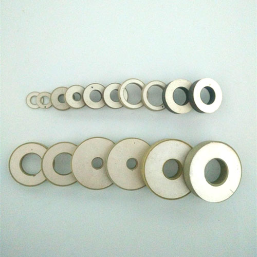
Preloaded ultrasonic transducers illustrate this distinction. Ceramic rings are held between mechanical parts, often using a central bolt. The preload must meet the transducer design requirements, but increasing torque without confirming the resulting load can damage the ceramic. Torque is an indirect measure of preload: thread friction, lubrication, washer condition, and joint geometry influence the relationship.
Uneven loading can be just as damaging as excessive preload. Nonparallel mating faces, burrs, tilted washers, or mismatched stack dimensions can concentrate force on a small region. A ring may also bind against a bolt or locating feature, introducing unintended lateral contact during tightening.
Useful controls go beyond issuing a torque value:
- Verify mating-face flatness, parallelism, cleanliness, and freedom from burrs.
- Check clearances around bolts and locating features against the assembly drawing.
- Validate the tightening sequence and tool behavior, including impact or overshoot.
- Establish the torque-to-preload relationship for the actual hardware and lubrication condition.
- Support thin discs or plates without forcing them flat against a distorted fixture.
If failures cluster at one angular position, investigate the fixture and contact surfaces before concluding that the ceramic batch is defective. Crack location is evidence, although it cannot prove the cause by itself.
Misalignment, insertion, and handling damage
A component should not become the alignment tool for the surrounding assembly. Forcing a ceramic disc into an undersized pocket, correcting stack misalignment by tightening, or pressing on an unsupported plate can create edge loading or bending. Interference-fit retention is particularly sensitive to tolerances and differential thermal expansion and requires a specifically validated design.
Damage can begin before installation. Hard tweezers, metal tray contact, dropped parts, or collisions during automated feeding may leave edge chips or fine cracks. Subsequent assembly stress can extend these defects, making the final operation appear responsible for damage that started earlier.
Use handling tools that distribute contact pressure and packaging that prevents part-to-part impacts. For automated placement, review pickup position, vacuum level, placement force, and release behavior. A nozzle that works well on a thicker component may be unsuitable for a thin ceramic plate.
Soldering creates thermal gradients—and lead wires add mechanical loads
During soldering, a small electrode area can heat much faster than the surrounding ceramic. Local expansion is constrained by cooler material, creating thermal stress. Uneven cooling adds another stress cycle. Risk depends on component thickness, soldering method, heat input, dwell time, and the way the part is supported.
The soldering process must also respect the material’s thermal limits and electrode compatibility. Excessive heating may impair polarization or electrical performance without producing a visible crack. Conversely, an acceptable electrical reading immediately after soldering does not establish that the ceramic is mechanically undamaged.
Use supplier-approved soldering guidance for the specific part. Where appropriate, controlled preheating can reduce temperature gradients, but it must remain within the permitted thermal exposure. Do not substitute a generic soldering recipe for a validated process.
Lead attachment deserves equal attention. Pulling a wire tight, bending it close to the joint, or allowing a stiff cable to move can transfer force into the electrode and ceramic. Provide strain relief outside the active element and avoid arrangements in which cable routing bends the component. Electrode lifting and ceramic cracking are different defects, but both can originate from the same handling practice.
Adhesive curing can leave stress locked into the assembly
Bonding appears gentler than mechanical clamping, yet it can create substantial residual stress. Adhesive shrinkage, an uneven bond line, and thermal expansion mismatch between ceramic and substrate can load the component during cure and cooling. A stiff adhesive may transmit substrate distortion directly into the ceramic.
More adhesive is not automatically safer. Excess material can create an inconsistent bond line or unintentionally restrain edges that need to remain free. Too little adhesive can leave unsupported areas that bend under later loading. The appropriate bond-line thickness and coverage depend on the required acoustic coupling, stiffness, environmental resistance, and geometry.
Review the complete bonding cycle: dispensing, placement pressure, fixture restraint, cure temperature, cooling rate, and release from the fixture. A part that survives curing while clamped may crack when released if the fixture has held a distorted assembly in place. Process qualification should include the finished, unrestrained condition—not only inspection inside the curing fixture.
Find the damage point before changing the process
The most useful investigation follows the component through assembly. Compare its condition at receipt, after placement, after lead attachment, after bonding, and after final tightening. Inspection frequency can be risk-based, but a failure investigation needs enough checkpoints to identify where the condition changes.
Record observations alongside component lot, fixture identity, tool settings, adhesive batch, cure profile, and any rework. Repeated failures associated with one fixture suggest a different investigation from failures distributed across incoming parts and several assembly stations.
Visual inspection under suitable magnification can reveal edge chips, surface cracks, and electrode damage. Lighting angle matters, especially near electrode boundaries. Hidden cracks may require a qualified nondestructive method appropriate to the geometry; neither a visual check nor any single electrical measurement detects every defect.
Capacitance, insulation resistance, impedance response, resonance behavior, or application-level output can help identify abnormal parts. Interpret these measurements against agreed acceptance criteria and comparable test conditions. Bonding, preload, temperature, and mounting can change electrical or acoustic behavior even when no crack exists. An abnormal result is a reason to investigate, not an automatic crack diagnosis.
Separate containment from corrective action
When a crack is confirmed, prevent the suspect component from progressing into service and assess whether other units share the same exposure. Do not assume that filling the crack with adhesive restores the original mechanical or piezoelectric properties. Any repair route requires explicit engineering approval and validation; replacement is generally the more defensible route for a cracked active ceramic element.
The consequence depends on the application. A damaged sensing element may lose sensitivity or produce unstable readings. In a power ultrasonic assembly, cracking can alter vibration behavior and contribute to further deterioration under operation. Acceptance decisions should therefore consider intended duty, failure consequences, and the equipment’s protective functions—not merely whether the device still produces a signal.
Change one suspected cause at a time where practical, then repeat the relevant inspection and functional checks. Reducing tightening force may stop visible cracking but leave a transducer inadequately preloaded. Choosing a softer adhesive may reduce residual stress but alter acoustic coupling. A corrective action must preserve the assembly’s intended function.
What to confirm with the ceramic supplier
Supplier discussions are most productive when they include the assembly drawing, contact surfaces, load path, soldering profile, bonding process, and photographs of the defect. Ask for component-specific handling guidance, permitted thermal exposure, dimensional tolerances, surface-quality requirements, and recommended inspection criteria. Application requirements should be translated into documented acceptance limits rather than informal descriptions such as “small cracks are acceptable.”
Weifang Jude Electronic Co. Ltd manufactures and supplies piezoelectric ceramics, sensor elements, ultrasonic components, and power transducers for applications including ultrasonic welding, cleaning, fault detection, flow measurement, and underwater acoustics. These applications place different demands on mounting and assembly. A process suitable for a low-power sensor should not automatically be transferred to a high-power ultrasonic stack.
Before releasing an assembly process, confirm that the selected Piezoelectric Ceramic Components and the surrounding mechanical design have compatible requirements. If cracks recur, the next step is to trace local stress and process history—not simply request stronger ceramics or lower every machine setting.

Thank you very much for writing to us. Please leave your message and contact information, we will reply to you within 24 hours.