

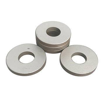
Capacitance sets much of the current a driver must supply to piezoelectric ceramics, even when the device consumes relatively little real power. For sinusoidal excitation away from significant mechanical resonances, the capacitive current is approximately Irms = 2πfCVrms. Doubling frequency, capacitance, or voltage therefore doubles this component of current. A driver with adequate voltage output can still fail to reproduce the required waveform if its current capability is insufficient.
Near resonance, capacitance alone is not enough to predict the electrical load. Mechanical motion, damping, mounting conditions, and acoustic loading alter terminal impedance. Reliable driver selection requires both a capacitive-current estimate and an impedance assessment under the intended operating conditions.
Why a capacitive load demands current
Applying voltage to a piezoelectric ceramic changes its electric polarization and produces mechanical strain. The electrodes also form a capacitor, so changing the applied voltage requires charge to move into or out of the device. For an approximately constant capacitance:
Q = CV
i(t) = C × dV(t)/dt
The second relationship is the practical driver-sizing rule: current depends on how quickly voltage changes, not just on its maximum value. Holding a steady DC voltage ideally requires no continuing capacitive current, although leakage and dielectric relaxation remain. A rapidly changing voltage can require substantial current even when the resulting displacement is small.
For a sine wave, differentiating voltage gives a current waveform that leads voltage by 90 degrees in an ideal capacitor. Its RMS magnitude is:
Irms = 2πfCVrms
Here, frequency is in hertz, capacitance in farads, and voltage in RMS volts. Peak current is √2 times RMS current for this sinusoidal, linear-capacitor approximation. The voltage must be the voltage across the ceramic terminals, rather than a supply-rail value or an unloaded amplifier specification.
A current calculation—and what it does not establish
Consider an illustrative ceramic load with a capacitance of 10 nF, driven at 40 kHz with 100 V RMS. Away from resonance, its calculated capacitive current is:
Irms = 2π × 40,000 × 10 × 10−9 × 100 ≈ 0.251 A
The corresponding peak current is approximately 0.355 A. Increasing capacitance to 20 nF raises the estimate to 0.503 A RMS without changing voltage or frequency. Increasing frequency to 80 kHz has the same effect.
This calculation does not mean the original ceramic dissipates 25.1 W. The product of RMS voltage and RMS current is approximately 25.1 VA of apparent power. An ideal capacitor returns its stored energy during each cycle, so its average real power is zero. Actual ceramics have dielectric and mechanical losses, while drivers have conduction, switching, and other circuit losses.
The distinction matters because low real power does not imply a lightly loaded amplifier. Output devices, wiring, connectors, and matching components must still carry the current. Driver heating also depends on circuit topology: a linear output stage and an energy-recovering switching stage can have very different losses when driving the same ceramic.
The capacitance value must match the operating conditions
A catalog capacitance is a measurement made under specified conditions, not an invariant description of the component. Test frequency, excitation amplitude, temperature, DC bias, and mechanical restraint can affect the measured value. Ferroelectric ceramics can show field-dependent behavior, making a small-signal measurement insufficient for predicting high-amplitude operation.
A value measured at 1 kHz with a low test voltage should therefore be treated as an initial estimate for a high-voltage ultrasonic application. It should not automatically be substituted into a 40 kHz current calculation as though all operating conditions were equivalent.
Mechanical boundary conditions deserve particular attention. A mechanically free ceramic can deform in response to the electric field, contributing to its measured electrical response. A clamped ceramic cannot deform in the same way. Free and clamped capacitance are consequently different concepts, and the applicable value depends on frequency and the mechanical configuration.
For a simple electrode arrangement, capacitance scales approximately as:
C ≈ ε0εrA/t
Increasing electrode area or reducing ceramic thickness increases capacitance, assuming comparable material properties and boundary conditions. This helps explain why thin-layer actuators can present demanding capacitive loads. It does not establish that a lower-capacitance component is a better replacement: changing geometry also changes electric field, displacement, force, and resonance behavior.
For multilayer components, the internal electrical connection matters as much as external dimensions. Layers connected electrically in parallel contribute to total capacitance. Comparisons based only on package size or rated voltage can therefore miss large differences in current demand.
Near resonance, use impedance rather than capacitance alone
A useful small-signal model around an isolated mechanical resonance is the Butterworth–Van Dyke equivalent circuit. It places a static capacitance, C0, in parallel with a motional branch containing resistance, inductance, and capacitance. These motional elements represent mechanical damping, inertia, and compliance through their electrical equivalents.
The terminal current is the phasor sum of current through these branches. It is not generally the arithmetic sum of their magnitudes. For sinusoidal operation in a sufficiently linear regime, the more complete relationship is:
Irms = Vrms/|Z(f)|
At the motional branch’s series resonance, its inductive and capacitive reactances cancel. The branch then presents primarily its motional resistance, which can produce a much higher current than the static-capacitance estimate suggests. Terminal phase is not necessarily zero at that exact frequency because the parallel capacitance still contributes current.
Near antiresonance, reactive currents in the branches can substantially cancel at the terminals, producing high input impedance and lower terminal current. This does not mean internal branch currents or mechanical stresses are negligible. Low current at the electrical connection is not, by itself, proof of low internal loading.
Mounting, preload, bonding, contact with a workpiece, and immersion in a fluid can alter resonance frequency and damping. An unloaded ceramic disk and a completed ultrasonic assembly should not be assumed to have the same impedance curve. In welding, cleaning, or liquid-coupled operation, the assembled and loaded transducer is the relevant electrical load.
A narrow-frequency impedance sweep is therefore more informative than a single capacitance reading for resonant systems. The sweep should identify impedance magnitude, phase, and the relevant resonances across the expected operating range. High-drive operation may also shift the response from its small-signal measurement, requiring verification at representative voltage and load.
Waveform shape changes the current requirement
The sinusoidal formula cannot be applied unchanged to pulses, ramps, or square waves. The general relationship, i = C × dV/dt, remains the starting point. A voltage transition ΔV completed in a rise time tr requires an approximate average current during that transition of:
I ≈ CΔV/tr
For example, changing the voltage across a 100 nF load by 100 V in 10 μs requires about 1 A during a linear ramp. Completing the same transition in 1 μs requires about 10 A. These are illustrative capacitive estimates; ringing, parasitic inductance, and electromechanical response can change the actual waveform.
Thus, a low pulse-repetition rate does not guarantee a low peak-current requirement. Fast edges can overload an output stage even when average power is modest. Current limiting then slows the voltage transition, changing displacement timing or the acoustic excitation waveform.
For triangular voltage, current is approximately constant during each linear ramp and reverses at the turning points. For a waveform containing harmonics, each harmonic produces capacitive current according to its own frequency. High-frequency content can consequently increase RMS current and driver heating beyond what a calculation using only the fundamental predicts.
Long cables add capacitance and inductance. Their capacitance increases off-resonance charging current, while their inductance can interact with the ceramic load to produce overshoot or ringing. Measuring only at the amplifier output can conceal differences between commanded voltage and the voltage actually delivered to the ceramic.
Separate dielectric heating from current-handling limits
For a sinusoidally driven, approximately linear dielectric, an estimate of dielectric loss is:
Pdielectric ≈ 2πfCVrms2tanδ
The loss tangent, tanδ, represents dielectric dissipation under the relevant measurement conditions. This relationship shows why increasing voltage deserves particular caution: capacitive current rises linearly with voltage, but estimated dielectric heating rises with voltage squared.
A low-field loss-tangent specification may not describe behavior at high electric field or elevated temperature. Near resonance, mechanical losses also contribute to heating and are not represented by this dielectric-loss estimate alone. Applying the formula to total resonant current would confuse distinct loss mechanisms.
Heating can change capacitance, losses, and resonance behavior, which in turn changes current demand. Thermal assessment should therefore use the intended duty cycle, mounting arrangement, cooling conditions, and mechanical load. A short burst test does not establish suitability for continuous operation.
Driver limits must likewise be separated into peak current, continuous RMS current, voltage swing, slew rate, and thermal capability. A stage may supply brief current pulses but not sustain the RMS current needed for continuous ultrasound. Another may meet its current rating yet distort the signal because its slew rate is inadequate.
Matching networks reduce source burden, not necessarily ceramic current
An inductor can compensate capacitive reactance around a selected operating frequency. In resonant drive circuits, this can reduce reactive current drawn from the source or improve the load presented to switching devices. It does not remove the current needed to charge and discharge the ceramic.
Current may instead circulate within the resonant network, and voltage across the ceramic can exceed the applied source voltage. Inductor current rating, winding losses, core behavior, insulation, and capacitor voltage stress must therefore be assessed using internal circuit conditions, not just supply current.
Compensation is also frequency-dependent. Capacitance tolerance, temperature changes, and mechanical loading can detune the system. A low source-current reading at one frequency is not sufficient evidence of adequate margins across the operating range.
Specifications that make a driver decision defensible
A useful component specification connects electrical measurements to their conditions. For capacitance, that means nominal value, tolerance, test frequency, test voltage, temperature, and mechanical state. For resonant applications, impedance magnitude and phase under representative loading are more directly useful than capacitance alone.
The drive requirement should define terminal voltage unambiguously as RMS, peak, or peak-to-peak, together with waveform, frequency range, duty cycle, and any DC bias. Confusing 100 V peak-to-peak with 100 V RMS creates a large error in both current and heating estimates. Maximum field, reverse-voltage restrictions, and temperature limits must also remain consistent with the ceramic’s ratings.
Validation should record terminal voltage and current together, including their phase relationship. Probe bandwidth and timing alignment matter when calculating real power, especially for strongly reactive loads. Tests should include plausible high-capacitance conditions and the lowest expected operating impedance, rather than only nominal room-temperature values.
Capacitance provides the baseline charging-current requirement. Impedance under mechanical load determines whether resonance increases or reduces terminal current, and waveform slew determines transient demand. A suitable driver must reproduce the required voltage while staying within all three constraints—not merely deliver the correct voltage into an unloaded output.

Thank you very much for writing to us. Please leave your message and contact information, we will reply to you within 24 hours.