

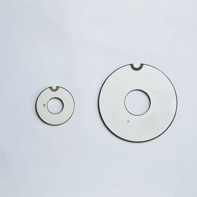
A ceramic element in an ultrasonic cleaner or precision positioning device can move even though it has no motor, gears, or sliding parts. Piezoelectric Ceramics convert voltage into motion through the inverse piezoelectric effect: an electric field changes the material’s internal polarization and crystal structure slightly, causing the ceramic to expand, contract, or deform.
The movement of a single element is usually small, but it can produce useful force or rapid vibration. Whether that motion becomes a controlled positioning step, an ultrasonic wave, or barely detectable movement depends on the ceramic’s polarization, electrode arrangement, dimensions, mounting, and electrical drive. These details explain why applying voltage to two apparently similar components may produce very different results.
From applied voltage to a change in shape
Many piezoelectric ceramics used in actuators and transducers are ferroelectric materials, such as lead zirconate titanate, commonly called PZT. Their crystal structure supports spontaneous electric polarization: the centers of positive and negative charge do not coincide. Regions with similarly oriented polarization are called domains.
Before poling, these domains point in different directions, so their responses largely cancel at the component level. During manufacture, a strong electric field is applied under controlled conditions to align enough of the domains in a preferred direction. This process gives the ceramic a useful overall polarization that remains after the poling field is removed.
Electrodes then provide a way to apply an operating electric field. The field changes the crystal lattice dimensions and, depending on the material and drive conditions, can also influence domain behavior. The combined response across the ceramic produces a measurable dimensional change. At modest fields, the relationship can often be approximated as proportional; at larger fields, nonlinear behavior becomes more important.
The ceramic does not need to heat up first to move. Thermal expansion can affect its dimensions during operation, but it is separate from the intended piezoelectric response. This distinction matters when a component moves immediately with voltage yet also drifts more slowly as the assembly warms.
The same material can work in the opposite direction. Mechanical stress produces an electrical response through the direct piezoelectric effect, which is used in sensing. Voltage-driven motion uses the inverse effect. An ultrasonic transducer may use both: it deforms to transmit sound and responds electrically when returning sound waves stress it.
Voltage matters through the electric field
A voltage rating alone does not describe how strongly a ceramic is being driven. The electric field depends on the distance between the electrodes. For a simple, uniformly electroded layer:
Electric field = applied voltage ÷ active layer thickness.
A thinner layer therefore experiences a stronger electric field at the same voltage. This is one reason multilayer actuators can operate at lower voltages than thick, single-layer elements. It does not mean the voltage can be increased without limit: allowable electric field, insulation, polarization stability, and mechanical stress still constrain operation.
For a simple longitudinal element operating approximately linearly, the strain can be expressed as:
Strain ≈ d33 × electric field.
Strain is the change in length divided by the original length. The coefficient d33 describes the response when the electric field and measured deformation are both along the polarization axis. Under unloaded conditions, with electrodes across that same active length, this gives an approximate displacement of d33 multiplied by the applied voltage.
This relationship is useful for understanding the mechanism, not for guaranteeing an assembled device’s travel. Actual displacement can differ because of loading, clamping, nonlinear response, temperature, and the electrical waveform. Datasheet displacement values should therefore be read together with their stated test conditions.
The electrode and polarization directions determine the motion
Voltage does not simply make every dimension grow. The direction of the electric field relative to the polarization determines which response is excited. A ceramic may extend in one direction while contracting in another.
For many commonly used poled PZT ceramics, a field aligned with the polarization produces longitudinal expansion and transverse contraction. Reversing the field can reverse the small-signal deformation, but a strong opposing field may destabilize or reverse polarization. Bipolar operation must stay within the component’s specified limits.
This directional behavior explains why a disc may be used for radial vibration, a stack for axial positioning, and a bonded strip for bending. Shape alone is not enough to identify the operating mode; polarization and electrode placement must also be known.
Making a small deformation useful
Stacking layers adds axial travel
A multilayer stack places many active ceramic layers mechanically in series. In a common arrangement, internal electrodes connect those layers electrically in parallel, so each layer experiences the applied drive voltage. Their individual extensions add along the stack.
For an ideal unloaded stack with similar layers, total displacement is approximately the number of active layers multiplied by d33 and the drive voltage. Real stacks depart from this simplified relationship, but it shows why adding layers can increase travel without requiring the entire stack thickness to be driven as one thick dielectric layer.
Stacks are useful when compact axial motion and substantial force are needed. They are not unrestricted push-pull devices. Brittle ceramic layers are generally less tolerant of tension, bending, and uneven contact than of appropriately distributed compression, so the load path and any specified preload matter.
Bending converts unequal strain into larger tip movement
In a bending actuator, a piezoelectric layer may be bonded to a passive layer, or two active layers may be driven to produce different strains. Because the bonded layers cannot freely change length independently, the assembly curves.
The tip displacement can be much larger than the direct dimensional change of one ceramic layer. The trade-off is lower output stiffness and force compared with a compact stack designed for axial loading. A bending element that offers visible travel is therefore not automatically the better choice for moving a stiff load.
Mechanical amplifiers use a related principle: they convert small actuator travel into larger output movement through flexures or other structures. Amplification changes the force, stiffness, and dynamic response available at the output; it does not create extra mechanical energy.
Steady positioning and ultrasonic vibration use the same effect differently
With a steady voltage, a piezoelectric actuator moves toward a new deformation and holds approximately that state. Maintaining a static position does not require continuous rotation or repeated strokes. The electrical behavior is largely capacitive, although leakage and dielectric losses mean that real operation is not perfectly loss-free.
An alternating voltage makes the deformation repeat. At sufficiently high frequency, this cyclic motion can generate ultrasound. In cleaning equipment, the transducer transfers vibration into the liquid through the assembly. In ultrasonic welding, a tuned mechanical structure transfers vibration toward the working interface.
Operation near a mechanical resonance can produce greater vibration amplitude than operation well away from resonance. That increase comes from the dynamic behavior of the complete system, not a change in the basic piezoelectric mechanism. The ceramic, attached masses, mounting, and surrounding medium all influence resonance.
A component selected for slow positioning cannot be assumed suitable for high-power ultrasonic operation. Repeated high-frequency deformation brings different requirements for mechanical losses, heat removal, fatigue, and drive control. Likewise, a resonant transducer’s vibration amplitude does not directly predict its useful static positioning travel.
The driver must also supply enough current to charge and discharge the ceramic’s capacitance. As frequency or voltage swing rises, current demand increases. A drive circuit may produce the expected voltage with no load but fail to maintain that waveform when connected to the transducer, reducing motion or introducing distortion.
When the movement is smaller or less stable than expected
A weak response does not necessarily mean the ceramic lacks piezoelectric activity. The first question is whether the electrical field, mechanical freedom, and measurement method match the intended operating mode.
- Confirm the active direction. Identify the polarization axis and electrode arrangement. Measuring thickness change will not fully describe an element intended primarily for radial or bending motion.
- Check the voltage at the component. Cable impedance, driver current limits, and capacitive loading can make the actual waveform different from the commanded signal, especially at high frequency.
- Examine mounting and load. Adhesive, rigid clamping, off-axis force, or excessive preload can restrict deformation. A fixture may absorb movement that would otherwise appear at the output.
- Separate displacement from vibration amplitude. A slow-position measurement and a resonant vibration measurement describe different operating conditions and require suitable instruments.
- Review temperature and drive limits. Heating changes material behavior and resonance. Excessive electrical or thermal exposure can also cause permanent degradation.
The distinction between free displacement and blocked force is especially important. Free displacement is travel with negligible opposing load. Blocked force is the force generated when movement is prevented. An actuator does not deliver both maxima simultaneously; its operating point depends on the stiffness of the load and assembly.
Precision positioning introduces two further effects. Hysteresis means that displacement depends partly on the voltage history, so the same voltage can correspond to different positions during increasing and decreasing drive. Creep is a slower displacement change after a voltage step. Neither necessarily indicates damage.
Where repeatable position matters more than simply producing motion, a displacement sensor and closed-loop controller can correct these deviations within the system’s capabilities. Open-loop voltage control may be sufficient for less demanding movement, but it should not be mistaken for exact position control.
Reading component specifications against the intended motion
Start by defining the required output: axial travel, bending displacement, shear movement, or vibration at a particular frequency. Then compare specifications measured under relevant conditions rather than ranking ceramics by a single coefficient.
A high piezoelectric coefficient can support greater strain per unit field, but material selection also involves dielectric loss, mechanical loss, stiffness, temperature behavior, and resistance to depolarization. Formulations optimized for sensitive displacement are not necessarily optimized for sustained high-power resonance.
For a positioning element, useful information includes displacement versus voltage, capacitance, stiffness, blocked force, hysteresis, mounting requirements, and allowable preload. For an ultrasonic element, resonance characteristics, operating mode, losses, drive limits, and the intended mechanical assembly deserve closer attention.
Safe operation requires more than staying below a nominal voltage. Reverse fields, excessive temperature, tensile loading, and local stress concentrations can damage a component or reduce its polarization. High-voltage drivers and charged capacitive elements also require appropriate electrical precautions. When electrode orientation, permissible drive, or mounting conditions are unclear, confirm them before energizing the part: those details determine whether the electric field becomes useful motion or avoidable stress.

Thank you very much for writing to us. Please leave your message and contact information, we will reply to you within 24 hours.