

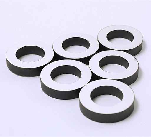
Acceptance testing for piezoelectric ceramic components is not a simple “pass or fail” exercise. A disc, ring, plate, tube, or custom-machined element can look correct, meet a basic capacitance check, and still behave poorly once it is bonded into an ultrasonic stack, exposed to elevated drive levels, or placed in a measurement system where signal drift matters. Quality teams need to verify the condition of the ceramic itself, but also whether its measured behavior supports the intended assembly and operating environment.
This matters across applications such as ultrasonic welding, cleaning, punching, flaw detection, flow measurement, underwater acoustics, sonar, length measurement, and oil-well instrumentation. The acceptance criteria for a low-power piezoelectric sensor will not be identical to those for a high-power transducer element. Still, the underlying discipline is similar: confirm traceability, inspect for defects, verify geometry, measure electrical and electromechanical response, and make sure the lot-to-lot variation is understood rather than ignored.
Acceptance begins with a usable specification
The most common weakness in incoming inspection is not the test equipment. It is an incomplete purchase specification. Terms such as “PZT disc,” “ultrasonic ceramic,” or “high-quality piezo element” do not define an acceptance condition. They describe a product family, not a controlled component.
Before receiving inspection starts, the quality plan should identify the ceramic composition or material grade, geometry, electrode configuration, polarization direction, dimensional tolerances, and the electrical properties that are critical to the application. It should also state the test conditions where those properties are measured. Capacitance, resonant frequency, impedance, dielectric loss, and coupling-related values can vary with temperature, fixture arrangement, excitation level, frequency range, and whether the component is free or already mounted.
For example, a radial-mode ring intended for an ultrasonic cleaning transducer should not be accepted solely because its outer diameter is in tolerance. Its resonance behavior, electrode integrity, and consistency with the mating stack are often more consequential. Conversely, in a precision sensing assembly, excessive thickness variation or unstable capacitance may create calibration issues even when the element produces an apparently normal output signal.
A practical specification separates characteristics into three groups: mandatory acceptance limits, values to be recorded for process control, and application-level tests completed after assembly. That distinction prevents a ceramic supplier from being held to an undefined system-level result while ensuring that critical incoming risks are not deferred until final product testing.
Verify identity, lot control, and polarization before testing performance
Traceability can seem administrative until a failure investigation begins. Piezoelectric ceramics are sensitive to material formulation, firing profile, machining method, electrode process, and polarization conditions. Mixing lots without records makes it much harder to identify whether a drift in transducer output comes from assembly, bonding, drive electronics, or a change in the incoming ceramic.
Incoming documentation should allow the receiver to connect the shipment to a material designation, production lot or batch, quantity, date information where required by the buyer, and inspection results agreed with the supplier. A certificate of conformance may be appropriate for routine deliveries, but it should not automatically replace verification for safety-sensitive or performance-critical components. The right balance depends on supplier history, process capability evidence, component criticality, and the consequences of field failure.
Polarization direction deserves specific attention. A ceramic element may be poled through its thickness, radially, axially, or in another defined direction depending on the design. Incorrect polarity marking, reversed electrode orientation, or an unspecified polarization axis can lead to low output, unexpected mode behavior, or assembly errors. Where polarity orientation matters, it should be marked in a durable and unambiguous way, or controlled through packaging and handling instructions.
Visual inspection is not cosmetic inspection
Piezoelectric ceramics are brittle, and small defects can become serious under mechanical preload, thermal cycling, or high-power vibration. Inspection should include the ceramic body, electrode surfaces, edge condition, and packaging condition. A chipped edge may be harmless in one low-stress sensor design but unacceptable in a bolted Langevin-type ultrasonic stack, where stress concentration can encourage crack propagation.
Inspectors should look for visible cracks, chips, delamination, pores exposed by machining, edge damage, contamination, incomplete metallization, electrode lifting, oxidation where relevant, and scratches deep enough to affect the active surface or assembly bond. Hairline cracks are particularly problematic because they may not produce an immediate electrical open circuit. Their effect can emerge only after torque is applied, the component is heated, or the transducer is driven near its intended amplitude.
Packaging deserves a quick but serious review. Loose ceramic rings rubbing together in transit, insufficient separation between plated surfaces, or moisture-contaminated packaging can create avoidable incoming defects. When recurring cosmetic damage is observed, the fix is often in packaging design and handling controls rather than in final inspection alone.
Dimensional checks should follow the physics of the component
Dimensional inspection needs to focus on features that affect resonance, preload, adhesive bondline, insulation clearance, and assembly alignment. For a simple disc, diameter, thickness, flatness, parallelism, and edge condition may be sufficient. For rings and tubes, inner diameter, outer diameter, wall thickness, concentricity, face parallelism, and squareness may all influence how the element loads in an assembly.
Thickness is often especially important because it directly relates to thickness-mode resonant behavior. However, measuring it carelessly can damage thin or fragile parts. Contact force from a measuring tool, dirt on the anvil, or measurement too near a chipped edge can give misleading readings. A documented sampling plan, calibrated equipment, and defined measurement locations are more valuable than taking a large number of inconsistent readings.
Do not assume that a part with the right nominal dimensions will automatically match the specified resonance. Ceramic material variation, electrode mass, machining tolerance, and test boundary conditions all play a role. Geometry and impedance testing should therefore support each other rather than be treated as substitutes.
Electrical acceptance: use an impedance curve, not one isolated number
A capacitance measurement is a useful screening tool. It can reveal an open electrode, a short circuit, a gross material inconsistency, or the wrong part family. But capacitance alone does not establish that a piezoelectric ceramic component is fit for ultrasonic or resonant service.
For resonant components, an impedance or admittance sweep around the relevant operating mode is usually much more informative. It can identify resonant and anti-resonant characteristics, impedance minima, excessive loss, split modes, abnormal spurious responses, and unusual variation within a lot. The test frequency range must be wide enough to capture the intended mode and nearby unwanted modes; a narrow sweep can make a problematic part appear acceptable.
Fixture discipline is essential. Probe pressure, contact cleanliness, cable compensation, fixture capacitance, grounding, and sample orientation can alter the result. If production acceptance uses an impedance analyzer, the work instruction should state the instrument setup, calibration approach, test leads, component support method, and pass/fail limits. “Measure resonance” is not a reproducible instruction.
Sampling plans must reflect the risk of hidden defects
Many suppliers and buyers use sampling inspection for established ceramic part numbers, especially when production volume is high and supplier performance is stable. That can be reasonable, but only if the sampling plan reflects what the test can and cannot detect. A visual sample may find shipping damage; it may not reveal a batch-wide shift in resonant frequency. A small electrical sample may miss sporadic cracks caused by a machining issue.
For new parts, redesigned geometries, changes in material source, or components used in high-consequence equipment, it is often prudent to increase inspection until the process is understood. Lot-level impedance trend data can be more useful than a single acceptance result because it shows whether the process is drifting toward a limit. Quality teams should have a defined escalation route when a lot is technically within tolerance but unusually close to a functional boundary.
This is also where supplier communication matters. Manufacturers with experience in piezoelectric components, ceramic sensors, ultrasonic piezo elements, and power transducers can often explain which characteristics are controlled at the ceramic stage and which must be validated after assembly. For applications served by suppliers such as Weifang Jude Electronic Co. Ltd—including powerful ultrasonic equipment, fault detection, measurement devices, and underwater acoustic systems—the most useful acceptance plan is usually built around the actual operating mode, not a generic ceramic checklist.
Separate component acceptance from transducer qualification
A compliant incoming ceramic is not proof that the finished device will meet its performance target. Adhesive selection, curing profile, bolt preload, backing material, matching layers, mechanical housing, wiring, and drive electronics can all shift frequency response and loss. The ceramic acceptance test should protect the assembly process from defective or inconsistent material; the final transducer test should verify the finished system.
The distinction is particularly important for high-power ultrasonic welding, washing, and punching equipment. A free ceramic element may show a clean impedance response, while the assembled stack develops excessive heating because of preload variation, poor mating surfaces, or operation too close to an unwanted vibration mode. In sensitive ultrasonic fault detection or flow measurement, the larger concern may be repeatability, noise, bandwidth, or signal stability rather than maximum mechanical amplitude.
Where product safety or regulatory compliance applies, the applicable end-product requirements should be reviewed separately. There is no single acceptance test package that automatically covers every piezoelectric application. Industry standards, customer specifications, electrical safety rules, environmental conditions, and intended use all need to be considered in the final verification plan.
A defensible acceptance record is part of the product
Inspection records should capture more than a stamp marked “accepted.” Record the lot, quantities received and sampled, measuring equipment used, environmental conditions where relevant, dimensional results, electrical test setup, observed defects, disposition, and any concession decision. When trends appear months later, this information is what allows a team to distinguish normal variation from a material or process change.
The best acceptance process is not necessarily the one with the most tests. It is the one that checks the failure mechanisms that matter for the specific component: cracks under preload, unstable resonance, electrode failure, dimensional mismatch, leakage, or lot inconsistency. If a requirement cannot be stated with a measurement method and a decision limit, it is not yet an effective acceptance requirement. Resolving that gap before production is far less expensive than discovering it in an ultrasonic stack, a field sensor, or an instrument already in service.

Thank you very much for writing to us. Please leave your message and contact information, we will reply to you within 24 hours.