

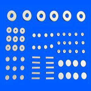
Material selection for medical piezoelectric ceramic components usually narrows down to one practical question: which ceramic can hold the required acoustic and electrical behavior under the real operating conditions of the device, not just on a catalog sheet. In imaging assemblies, that often means balancing sensitivity, bandwidth, dielectric stability, and manufacturability. In therapeutic systems, the same selection shifts toward power tolerance, thermal behavior, mechanical robustness, and resistance to depolarization during sustained drive. The wrong choice may still function in a prototype, yet drift, heat excessively, or lose repeatability after bonding, sterilization exposure, or continuous excitation.
The first material split is commonly between hard and soft piezoelectric ceramics, usually within lead zirconate titanate families. Soft formulations are generally preferred where high electromechanical coupling, strong sensitivity, and easier excitation are needed. They can support efficient transmit and receive behavior in many ultrasound imaging structures, especially where broad response and signal quality matter more than extreme power loading. Hard formulations trade some sensitivity for lower dielectric loss, better resistance to self-heating, and improved stability under high electric fields. That makes them more suitable when the component must operate for long duty cycles or deliver stronger acoustic output, as in certain therapy heads or power-focused ultrasonic stages integrated into medical equipment.
A common mistake is to compare only one or two headline properties, such as d33 or coupling coefficient, and assume the higher number defines the better component. In medical assemblies, resonance behavior, mechanical quality factor, dielectric constant, aging characteristics, and coercive field all interact with the final stack design. A ceramic with very high sensitivity may complicate matching, narrow the usable processing window, or become vulnerable to performance drift if the bonding layer, backing material, and housing generate stress concentrations. Selection is therefore inseparable from the transducer architecture.
Imaging-Focused Material Priorities
For diagnostic ultrasound, the ceramic often needs to support short pulses, controlled damping, and a frequency response that fits the intended imaging depth and resolution. A material with high electromechanical coupling can improve conversion efficiency, but broad imaging performance depends just as much on how the ceramic behaves once it is lapped to thickness, metallized, diced, bonded, and acoustically matched. Thin sections used for higher frequencies may become more fragile during handling, and edge defects introduced during machining can later appear as unstable impedance curves or channel-to-channel inconsistency in arrays.
In phased arrays and multi-element probes, uniformity matters as much as absolute performance. Small variations in thickness, density, polarization quality, or electrode coverage can create uneven resonance and phase response across elements. That irregularity may not be obvious in a simple electrical inspection, yet it can degrade beam steering, focusing, and image consistency after final assembly. For this reason, material selection should include tolerance capability, not just nominal properties. A ceramic that is slightly lower in peak specification but consistently processable across many small elements may be the better choice.
Back-end integration also changes the selection logic. If the acoustic stack uses heavy backing for strong damping, the ceramic may need enough coupling to preserve useful output after losses are introduced. If the design aims for narrower bandwidth, the material may tolerate a different mechanical quality factor. In miniature devices, thermal expansion mismatch between ceramic, flex circuits, epoxies, and front layers deserves attention because repeated heating and cooling can alter preload and resonance over time.
Therapy and High-Power Operating Conditions
Therapeutic ultrasound pushes the ceramic into a different regime. The priority shifts from receiving faint echoes to delivering stable acoustic energy over longer intervals. Under these conditions, dielectric loss and internal heating become selection drivers. A material that performs well in low-power testing may show unacceptable temperature rise once driven continuously near resonance. If heat cannot leave the structure efficiently, polarization can weaken, adhesive layers may soften, and the acoustic interface may change enough to move the operating point.
Hard piezoelectric ceramics are often considered in these cases because they usually offer higher mechanical quality factor and better resistance to depolarization under strong drive. Even then, the final behavior depends on geometry and boundary conditions. A large disc, ring, or bowl-shaped element used in therapy may encounter radial modes, spurious resonances, or localized stress fields that are not visible when evaluating bulk material data alone. It is often necessary to review impedance signatures from the finished or near-finished geometry rather than relying on material tables.
Another point frequently missed is that high-power performance is not determined by ceramic alone. Electrode thickness, soldering temperature, compression scheme, heat-sinking path, and potting materials all affect survivability. If the ceramic is selected without considering these adjacent materials, the result may be premature cracking, electrode lifting, or a gradual drop in output after repeated cycles. In therapy heads, the acceptable material is usually the one that maintains stable behavior through the whole thermal and mechanical stack, not the one with the strongest initial amplitude.
Frequency Range and Geometry Constraints
Frequency requirement changes both material choice and processing difficulty. Lower-frequency medical transducers often use thicker ceramics, which can be mechanically robust but may support unwanted lateral modes if diameter-to-thickness ratio is not controlled. Higher-frequency parts require thinner sections, tighter flatness, and more careful electrode definition. At small thicknesses, lapping damage, residual stress, or slight nonparallelism can cause measurable shifts in resonance. A ceramic formulation that is easy to pole in bulk form may still be difficult to process into very thin, stable elements.
For ring and tube geometries, wall thickness tolerance becomes especially important when the component is used in focused or circumferential emission structures. For diced arrays, kerf quality and edge integrity affect electrical isolation and acoustic crosstalk. These are not just machining details; they influence whether a material remains practical at the required size scale. During evaluation, it is worth asking for data or samples that reflect the actual geometry rather than a generic test coupon.
Electrical and Acoustic Matching Considerations
Medical piezoelectric ceramic components do not operate as isolated materials. Their effective performance depends on the surrounding electrical network and acoustic path. A high dielectric constant can be useful when compact capacitance is needed, but it may also alter impedance matching requirements in the driving electronics. Likewise, a ceramic with favorable free-state resonance may behave quite differently after it is bonded to matching layers or loaded by fluid contact.
This is one reason early sample evaluation should include both free and mounted measurements. Free impedance data can reveal the intrinsic material response and identify gross defects. Mounted testing begins to show whether the ceramic remains stable once constrained, damped, and exposed to the same interfaces expected in the final device. If mounted response varies sharply between builds, the issue may not be the material family itself but the way that family reacts to process variation.
- For imaging stacks, broadband response after assembly is often more informative than standalone sensitivity.
- In power-driven structures, a modestly lower coupling factor may be acceptable if dielectric loss stays lower during sustained excitation.
- Where electronics have limited tuning margin, capacitance spread and impedance consistency can matter more than peak output.
Process-Induced Risk During Manufacturing
Material choice should be reviewed together with the production route. Ceramics that look equivalent in specification can respond very differently to cutting, drilling, grinding, plating, poling, or high-temperature joining. Some compositions are more prone to microcracking during dicing. Others may be sensitive to thermal excursions during solder attachment or conductive epoxy cure. If the component will be brazed, clamped, or prestressed, the coercive field and fracture tendency deserve careful attention.
Poling quality is another area where selection and process cannot be separated. Poorly controlled poling may leave uneven domains, resulting in unstable output and wider spread in resonance. A material with a narrow effective poling window can be difficult to reproduce at scale. Conversely, a composition with slightly less aggressive nominal properties may offer better lot-to-lot stability because the process window is wider and less sensitive to small temperature or field deviations.
Metallization should not be treated as a trivial final step. Electrode adhesion, thickness, coverage pattern, and compatibility with subsequent joining materials influence both electrical reliability and acoustic damping. In small medical elements, excess electrode mass can shift resonance enough to matter. In higher-power parts, weak adhesion may lead to local heating or delamination under cyclic loading.
Incoming Evaluation and Qualification
When screening candidate materials, it helps to compare them through the same sequence they will experience in production: dimensional inspection, impedance analysis, dielectric measurement, assembly into a representative stack, then thermal and drive testing under realistic duty conditions. Skipping directly to room-temperature bench output often hides the failure modes that appear later. A component can pass an initial acoustic test and still be unsuitable if its resonance drifts after adhesive cure, if capacitance spreads too widely after dicing, or if output falls after repeated power exposure.
Storage and transport also deserve attention. Piezoelectric ceramics are brittle and can pick up edge damage from vibration, poor tray support, or impact during shipment. Moisture exposure may not directly destroy the ceramic body, but it can affect packaging materials, solderability of electrodes, or contamination at bonding interfaces. Incoming inspection should therefore include both electrical checks and simple visual controls around edges, corners, and plated surfaces.
Where long-term stability matters, aging behavior should be treated as a planning input rather than a surprise discovered late in validation. Piezoelectric properties can shift over time after poling, and that shift may accelerate if the part experiences elevated temperature or repeated high-field operation. If the application has tight frequency tolerance or output consistency requirements, qualification should include enough elapsed-time observation to detect whether the chosen material remains inside the acceptable band after processing and storage.
Common Selection Errors
One recurring error is choosing the ceramic before fixing the acoustic stack concept. Another is assuming that a material successful in industrial ultrasonics will transfer directly into a medical imaging or therapy assembly without adjustment. Similar operating frequencies do not guarantee similar damping, thermal loading, or sterilization exposure. It is also easy to overvalue laboratory sample data taken from large, idealized discs when the final device uses tiny diced elements, curved parts, or bonded composites.
A separate problem appears when evaluation teams compare different suppliers using non-equivalent test conditions. Resonance mode, electrode pattern, sample dimensions, and clamping method can all change the measured result. Any comparison that does not normalize these factors may rank materials inaccurately. The useful question is whether a given ceramic can be produced repeatedly in the intended form and remain stable after integration, not whether one isolated sample produced the highest reading in a favorable setup.
Selection becomes more reliable when material data, processing limits, and assembled performance are reviewed together. In practice, the strongest candidate is often the ceramic that remains predictable across machining, bonding, drive loading, and time, while still meeting the acoustic target of the device.

Thank you very much for writing to us. Please leave your message and contact information, we will reply to you within 24 hours.