

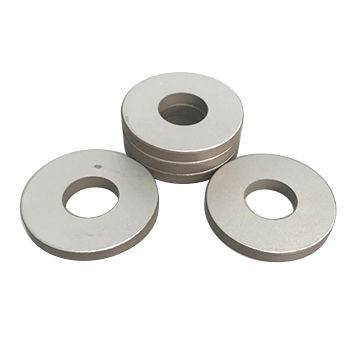
Cracking and depoling in Piezoelectric Ceramic Components can turn a stable ultrasonic system, sensor, or power transducer into an intermittent and frustrating service problem. The failure may appear as reduced amplitude, frequency drift, unstable readings, excessive heating, poor welding performance, or a device that works briefly and then fails under load. In more severe cases, a visible fracture is found when the assembly is opened. In others, the ceramic looks intact but has lost much of its piezoelectric response.
For after-sales maintenance personnel, the key question is rarely just “Is the ceramic damaged?” The more useful question is: What operating or assembly condition caused the damage, and will the replacement part face the same condition? Replacing a failed piezo element without identifying the root cause often leads to repeated downtime, avoidable warranty claims, and uncertainty at the customer site.
Cracking is primarily a mechanical failure, although electrical and thermal stresses often trigger it. Depoling, also called depolarization, is an electrical-material failure in which the aligned domains inside the ceramic lose their orientation. The two problems can occur separately, but they frequently appear together because the same overload event can generate heat, stress, and abnormal electric fields.
Start by separating a crack from a loss of polarization
A cracked piezoelectric ceramic component may show a visible radial, edge, or through-thickness fracture. Yet many cracks are hairline fractures hidden beneath electrodes, bonding layers, protective coatings, or compression hardware. They can cause changes in capacitance, insulation resistance, resonant frequency, impedance shape, or output consistency.
Depoling is less obvious. A depolarized ceramic can remain physically whole while delivering much lower displacement, sensitivity, or acoustic output. In an ultrasonic welding stack, this may present as poor energy transfer and an extended process cycle. In a measurement sensor, it may appear as signal loss, poor repeatability, or a calibration value that will not hold. In underwater acoustic and sonar equipment, the result may be weak transmission or reduced receiving sensitivity.
A practical distinction is that a crack often produces an abrupt electrical or mechanical change, while gradual depoling may first show as declining performance during high-duty operation. This is not an absolute rule. A severe electrical event can depole a ceramic immediately, and a small crack can create a gradual decline as moisture enters or stress propagates.
Mechanical stress: the most familiar cause, but not always the obvious one
Piezoelectric ceramics are strong in compression but relatively brittle in tension, bending, shock, and point loading. A component may survive normal bench testing yet crack after installation because the real stress path is different from the intended one.
Uneven clamping and excessive preload
Many high-power ultrasonic assemblies use preloaded piezoelectric rings or discs clamped between metal masses. Correct preload helps keep the ceramic under compression during vibration. Too little preload allows tensile stress during operation; too much preload can crush edges, damage electrodes, or introduce microcracks. The danger is not only the torque value. Uneven contact faces, a tilted bolt, burrs, distorted end masses, or a washer that does not sit flat can concentrate the load on one area of the ceramic.
When inspecting a failed stack, look beyond the ceramic itself. Check whether mating surfaces are clean, flat, and parallel. Inspect the central bolt for thread damage or bending. Verify that insulating sleeves, electrode tabs, spacers, and washers are installed in the correct order. A small assembly error can create a large local stress concentration once the transducer begins vibrating.
Bending loads and poor structural support
Piezoelectric Ceramic Components are not intended to compensate for a misaligned horn, probe, sensor housing, or cable assembly. If a transducer is mounted where the load is off-axis, vibration can introduce bending moments into the ceramic stack. A rigid cable pulling on a small sensor, a probe contacting a workpiece at an angle, or a poorly supported ultrasonic tool can all transfer unwanted force back to the active element.
Transport and handling also deserve attention. Dropping a component onto a hard bench, overtightening a housing, or gripping a ceramic with pliers may create damage that is not immediately visible. The unit may pass a basic continuity check and fail only after it is exposed to vibration or elevated voltage.
Resonance mismatch and abnormal vibration
High-power piezo systems are particularly vulnerable when operated away from their designed resonance or with an unsuitable mechanical load. A worn horn, loose booster, cracked radiating surface, or incorrectly tightened joint changes the resonance behavior of the complete system. The ceramic then sees increased stress and heat instead of efficiently converting electrical energy into useful motion.
Maintenance teams should avoid assuming that the generator is the only source of an overload alarm. A generator may be responding correctly to a mechanical mismatch downstream. Before fitting replacement ceramics, inspect the entire vibration path: converter, booster, horn or sonotrode, mounting interfaces, and the process load.
Thermal stress can crack ceramics and quietly erase performance
Temperature is a common thread in both cracking and depoling. Piezoelectric ceramics generate internal heat through dielectric loss, mechanical loss, and imperfect coupling. External heat may come from welding processes, hot equipment enclosures, sterilization cycles, process fluids, or nearby power electronics. If heat cannot leave the assembly, the temperature inside the ceramic can be much higher than the temperature measured on the outer housing.
Rapid temperature changes are especially risky. Ceramic, metal electrodes, adhesives, and housings expand at different rates. A component that is heated quickly and cooled with forced air or cold liquid can experience thermal shock. Repeated thermal cycling may also fatigue an adhesive joint or clamping structure, changing the preload and creating new stress points.
Depoling occurs when the ceramic is heated close to or above its material-specific depoling limit. This limit is not simply the Curie temperature. Useful piezoelectric properties can decline at temperatures well below the point where the material completely loses its ferroelectric state. Once significant depoling has occurred, cooling the part generally does not restore its original performance. Re-poling may be possible under controlled manufacturing conditions for certain materials and geometries, but it is not a routine field repair.
When a component repeatedly runs hot, do not treat cooling as an afterthought. Investigate duty cycle, drive frequency, mechanical loading, ventilation, heat sinking, mounting contact, and generator tuning. A replacement part with the same material grade may fail again if the operating environment remains unchanged. In some applications, the correct solution is a ceramic formulation selected for higher temperature stability rather than a simple like-for-like replacement.
Electrical overstress: voltage alone does not tell the whole story
Electrical overstress can depole, arc, or puncture piezoelectric ceramics. It is often caused by excessive drive voltage, but peak voltage, waveform quality, frequency, duty cycle, temperature, and mechanical boundary conditions all matter. A drive setting that is acceptable during a brief unloaded test may become destructive during continuous production.
Alternating electric fields opposite to the original poling direction are a direct depoling risk. Excessive field strength can disrupt domain alignment even when the ceramic does not visibly overheat. High electric fields may also create localized dielectric breakdown, particularly near electrode edges, defects, contamination, or areas where the ceramic has already been mechanically stressed.
Uncontrolled resonance is another important electrical-mechanical interaction. If the generator tracks incorrectly, if the load changes suddenly, or if a damaged transducer shifts its resonant point, current can rise sharply. The resulting internal heating may be mistaken for a material defect. A useful diagnostic step is to compare impedance or admittance data from the suspect unit with a known-good unit of the same design. Changes in resonance, anti-resonance, capacitance, and mechanical quality factor can reveal whether the issue is mainly mechanical, electrical, or both.
Pay particular attention to power supply faults, damaged cables, poor grounding, moisture-related leakage, and switching transients. A ceramic rarely “sees” only the nominal output listed on the controller. Measuring the actual waveform under realistic operating conditions is more informative than relying on panel settings alone.
Moisture, contamination, and electrode damage are often secondary causes
Moisture does not usually crack a properly protected ceramic by itself, but it can accelerate failure. Water, conductive dust, oil residues, cleaning chemicals, or flux residues can reduce insulation resistance and create leakage paths across electrodes. In high-frequency or high-voltage service, that leakage becomes heat. Corrosion at electrode interfaces can further increase resistance, producing localized hot spots and unstable performance.
Electrode damage deserves a close inspection. Scratched metallization, poorly soldered leads, excessive soldering heat, or a lifted electrode can alter current distribution. When soldering connections near a piezo element, prolonged heat input and mechanical force on the terminal should be avoided. Flexible lead support is usually safer than allowing cable movement to load the electrode directly.
For components used in ultrasonic cleaning, fluid measurement, oil well measurement, underwater sound, or other exposed environments, sealing integrity matters as much as electrical performance. A housing leak may be the initiating event, while depoling or cracking is the final symptom.
A field-oriented diagnostic sequence
When a failed unit reaches the service bench, resist the urge to immediately dismantle the stack. Some evidence is lost once preload is released. Record the reported symptoms, operating hours, process conditions, alarm history, drive settings, and whether the failure was sudden or progressive.
- Inspect externally. Look for impact marks, loose hardware, discoloration, overheated insulation, fluid ingress, worn mating parts, and evidence of improper assembly.
- Measure basic electrical condition. Check continuity where applicable, insulation resistance, capacitance, and dielectric loss using appropriate equipment and test limits.
- Perform impedance analysis. Compare resonant behavior with specification data or a reference component. A broadened or shifted resonance peak can indicate cracking, altered preload, bond failure, or material degradation.
- Review the mechanical assembly. Confirm torque procedures, contact flatness, alignment, and the condition of horns, masses, mounts, and fasteners.
- Assess thermal history. Identify sustained high duty cycles, poor cooling, blocked airflow, excessive process heat, or abnormal temperature rise under load.
- Verify the actual drive signal. Check voltage, current, waveform, frequency tracking, and behavior during the customer’s real operating cycle.
This sequence helps prevent a common mistake: labeling every weak transducer as “depoled” without checking for a loose stack, cracked horn, failed cable, or generator mismatch.
Corrective actions that reduce repeat failures
Once the cause is understood, corrective action should address the assembly and the operating conditions, not merely the damaged component. Replace cracked ceramics rather than attempting to reuse them. A crack can propagate unpredictably under vibration, and the electrical behavior of a damaged ceramic is no longer dependable. Clearly depolarized components should also be replaced unless a controlled factory re-poling process has been specifically approved for that product.
For rebuilt transducers, use clean, flat mating surfaces and the specified clamping method. Apply preload consistently with calibrated tools and approved procedures. Do not substitute washers, insulating parts, adhesives, or electrode arrangements without confirming their suitability. Material changes can alter stiffness, electrical isolation, thermal transfer, and resonant behavior.
Where high temperature is unavoidable, select Piezoelectric Ceramic Components designed around the real thermal and duty-cycle demands. Where mechanical shock or bending is present, improve mounting support and isolate the ceramic from external load paths. Where the drive is unstable, correct generator settings and verify resonance tracking before returning the equipment to service.
Manufacturers such as Weifang Jude Electronic Co. Ltd support applications ranging from ultrasonic welding and cleaning to sensing, flow measurement, fault detection, and underwater acoustic systems. In these varied applications, a useful replacement discussion includes more than dimensions and capacitance. Service teams should provide the operating frequency, drive condition, duty cycle, mounting arrangement, temperature exposure, load type, and observed failure mode. That information makes it easier to evaluate whether the original component design remains appropriate.
What a durable repair looks like
A durable repair is not simply one that restores output on the bench. It is one that remains stable after the equipment returns to its real load, temperature, vibration level, and production schedule. Cracking and depoling are warning signs that energy is going somewhere it should not: into concentrated stress, excess heat, leakage, or an unstable electrical field.
By treating the piezo ceramic, its mechanical stack, its electrical drive, and its operating environment as one connected system, after-sales teams can diagnose failures with far more confidence. That approach protects the replacement component, shortens repeat service calls, and preserves the accuracy and reliability that piezoelectric devices are expected to deliver.

Thank you very much for writing to us. Please leave your message and contact information, we will reply to you within 24 hours.