

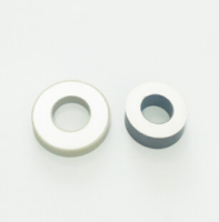
A high-voltage piezo actuator is only as reliable as the ceramic element at its core. Selecting piezoelectric ceramic components by looking only at a high d33 value or an attractive displacement figure often leads to poor results once the actuator is assembled, driven repeatedly, or exposed to real operating conditions. The specification needs to begin with the required motion and load, then work back through voltage, field strength, geometry, frequency, mounting, and expected service life.
The practical question is not “Which piezo ceramic has the highest output?” It is: which component can produce the required motion and force at the intended electrical and mechanical operating point without premature depolarization, dielectric failure, excessive heating, or unstable performance? A ceramic that performs well in a low-force positioning device may be unsuitable for a fast, high-voltage stack actuator. Likewise, a material chosen for resonance-driven ultrasonic equipment is not automatically the right choice for quasi-static precision motion.
Start with the actuator duty, not the material data sheet
Before comparing piezoelectric ceramic components, define what the actuator must do at the assembly level. The ceramic does not operate in isolation: electrodes, preload hardware, adhesive layers, flexures, housings, and the driven load all affect the result.
- Motion requirement: Specify free displacement, working displacement under load, resolution, and whether motion must be repeatable over many cycles.
- Load condition: Identify static force, dynamic force, stiffness of the load, shock loads, and whether the actuator must hold position after motion.
- Drive profile: Record maximum voltage, polarity, waveform, switching rate, dwell time, and duty cycle. Peak voltage alone is not enough.
- Operating mode: Distinguish between slow positioning, fast switching, vibration generation, impact action, or resonance operation.
- Environment: Include temperature range, humidity, vacuum or fluid exposure, electrical noise, contamination, and available space.
These inputs determine whether a monolithic plate, multilayer stack, ring, tube, bimorph, or custom-shaped ceramic is appropriate. For example, a long stroke with moderate force may favor a mechanically amplified arrangement, while a compact high-force movement commonly leads toward a stacked configuration. Choosing the form factor after selecting a material can force unnecessary compromises in voltage, stress, and insulation design.
Voltage rating must be evaluated as electric field
High-voltage actuator specifications are frequently written as a simple maximum voltage. That is incomplete because the ceramic responds to electric field, which depends on both voltage and the thickness of the active ceramic layer. The same applied voltage can be modest across a thick element and severe across a thin layer.
For a single-layer ceramic plate, disk, or tube, the field is broadly related to the applied voltage divided by the distance between electrodes. In multilayer piezo stacks, each internal ceramic layer sees the voltage across that individual layer, not the overall stack height. This is why multilayer designs can achieve useful displacement at relatively low external voltages, while single-layer components may require much higher drive voltages for comparable field conditions.
A robust specification should state the normal operating voltage, the highest transient voltage, polarity reversal conditions, and the permitted field range for the chosen material and geometry. It should also leave a realistic margin below the electrical limits. Repeated operation near a material’s limit can accelerate leakage, local heating, dielectric breakdown, or loss of polarization, especially where electrode edges, surface defects, or assembly stress concentrate the field.
Do not assume that bipolar drive is harmless because the waveform is symmetrical. Many piezoelectric ceramics are polarized in one direction and have different tolerance for fields applied opposite to that direction. If reverse voltage is expected during startup, shutdown, resonance overshoot, or control instability, that condition must be included in the component requirement rather than treated as an exception.
Displacement, blocking force, and stiffness are a linked decision
Free displacement is useful for comparing candidate ceramic elements, but it is rarely the motion available in a finished machine. Once the actuator pushes against a load, displacement decreases as output force rises. The relationship is controlled by actuator stiffness and load stiffness.
A component with high free stroke but low stiffness can be disappointing when it is attached to a rigid mechanism. Conversely, a stiff stack can generate substantial force but may provide less practical travel unless the mechanical design uses leverage or a flexure amplifier. The best choice depends on the load line, not on the largest catalog displacement or highest stated blocking force.
It is also important to separate actuator force from structural strength. A ceramic may produce a high blocking force while still being vulnerable to tensile stress, bending, edge chipping, or uneven contact pressure. Piezoelectric ceramics are strong in compression but comparatively brittle in tension. A high-force specification therefore needs an explicit mechanical boundary: allowable preload, maximum external load, mounting flatness, and restrictions on side loading.
Choose soft or hard material behavior for the real operating mode
Piezoelectric materials are often described broadly as “soft” or “hard.” The terms are useful only when tied to the application. Soft ceramics generally provide higher electromechanical response and can be attractive when displacement sensitivity matters. Their tradeoff is typically higher dielectric and mechanical loss, which can create more heat in high-frequency or high-duty operation.
Hard ceramics are commonly selected for powerful ultrasonic transducers, vibration systems, and other resonance-driven equipment because they are better suited to sustained, high-power cycling. Their lower loss behavior can be more valuable than maximizing the low-frequency displacement coefficient. In a high-voltage actuator that operates slowly with limited duty cycle, a soft material may be appropriate. In an actuator that cycles rapidly or works near resonance, material loss and thermal behavior can become the controlling factors.
The error is to treat “high piezoelectric coefficient” as a universal indicator of actuator quality. A coefficient describes part of the conversion behavior under defined conditions; it does not independently predict heat generation, usable voltage range, mechanical durability, or finished-system performance.
Frequency response changes the specification
Every piezo actuator has mechanical resonances determined by its ceramic geometry, electrodes, preload, mounting structure, and attached load. Near resonance, displacement can rise sharply, but so can current demand, stress, heat, and sensitivity to small changes in the assembly. That behavior may be desirable in ultrasonic welding, cleaning, punching, or acoustic transducers. It is usually undesirable in a precision positioning stage unless the system is intentionally designed and controlled around resonance.
For non-resonant actuation, specify the required usable bandwidth under the actual load and identify any frequencies that must be avoided. For resonant operation, specify the intended mode shape, resonant frequency range, temperature effects, drive limits, and cooling arrangement. A component cannot be selected accurately from its free-state resonance alone because clamping and mass loading shift the resonant behavior.
Electrical capacitance deserves the same attention. Piezo actuators are capacitive loads, and drive current rises with capacitance, voltage swing, and operating frequency. A power supply that can reach the required voltage but cannot deliver the necessary reactive current may produce waveform distortion, slower movement, unstable control, or overheating. Include capacitance tolerance and the expected frequency range in the driver compatibility review.
Geometry, electrodes, and assembly details often decide reliability
The shape of the ceramic determines not only the direction of motion but also how stress and electric field are distributed. Plates and stacks are commonly used for axial expansion. Tubes can create radial or bending motion. Rings and disks are useful where axial vibration or radial modes are required. Custom shapes may integrate more easily into a mechanism, but sharp corners, thin unsupported features, and complex electrode patterns require careful review because they can introduce stress concentrations and localized electrical loading.
Electrode design is not a cosmetic detail. Electrode material, coverage, edge location, lead attachment, and insulation clearance influence contact resistance and voltage endurance. In high-voltage assemblies, the external insulation system must be designed around the complete actuator, not just the ceramic’s nominal dielectric strength. Humidity, residue from processing, conductive dust, and poorly controlled adhesive fillets can create leakage paths or surface tracking outside the active ceramic body.
Preload is another area where specifications are often too vague. Many stack actuators require compressive preload to protect the ceramic from tensile loads and dynamic shock. The preload should remain within the intended range across temperature and throughout the full motion cycle. Excessive preload can reduce usable movement or damage the component; insufficient preload can allow tensile stress during reversal or impact. The preload mechanism must also apply force evenly. A tilted interface or rough contact face can concentrate stress at one edge and cause cracking.
Define reliability in terms of the expected service conditions
“Long life” is not a sufficient requirement for piezoelectric ceramic components. Reliability should be linked to the conditions that cause degradation: voltage field, temperature, cycle rate, mechanical stress, humidity, and electrical connection quality. A component used for occasional calibration movement faces a very different risk profile from one used in continuous pulsed production equipment.
For demanding applications, request characterization relevant to the intended use rather than relying only on room-temperature material values. Useful discussions with a supplier include polarization direction, electrode configuration, dimensional tolerances, capacitance range, insulation resistance expectations, material batch consistency, and recommended mounting or curing practices. Where the actuator will be part of a safety-sensitive or costly assembly, prototype evaluation should reproduce the final load, drive waveform, enclosure, and temperature conditions as closely as possible.
Manufacturing capability matters because ceramic processing, metallization, polarization, machining, and inspection all influence consistency. Suppliers such as Weifang Jude Electronic Co. Ltd provide piezoelectric ceramics and related transducer components for applications including ultrasonic equipment, measurement devices, and underwater acoustic systems. When reviewing any supplier, the useful question is whether it can support the required geometry, electrode arrangement, material behavior, and quality documentation for the intended actuator, rather than whether it offers a broad component catalog alone.
A practical specification sequence
- Define working displacement and force at the load, including the mechanical stiffness of the surrounding structure.
- Set the drive waveform, normal and transient voltage limits, polarity conditions, frequency range, and duty cycle.
- Select the actuator architecture: single-layer element, multilayer stack, tube, ring, bender, or a custom geometry.
- Match the material behavior to the operating mode, especially whether the device is used for precision motion, pulsed actuation, or resonant power transmission.
- Specify mechanical boundaries: preload, compression direction, side-load limits, mounting flatness, and shock exposure.
- Review capacitance and driver capability together, including current demand at the highest operating frequency.
- Define environmental exposure and the external insulation strategy for the complete actuator assembly.
- Validate representative samples under actual electrical, thermal, and mechanical conditions before freezing the design.
This sequence prevents a common procurement problem: ordering a ceramic component that matches a drawing and a nominal voltage but does not match the actuator’s real load or operating cycle. The most useful component specification is therefore a short, testable set of electrical, mechanical, environmental, and integration requirements. It gives the supplier enough context to recommend an appropriate material and gives the design team a clear basis for comparing alternatives.
Questions that expose weak specifications
Can the component be driven at its rated voltage continuously?
Not necessarily. A voltage rating must be read together with waveform, frequency, temperature, material loss, and cooling conditions. Continuous high-frequency operation can create much more heat than intermittent low-frequency movement at the same voltage.
Is a higher displacement coefficient always better for a high-voltage actuator?
No. Higher response can be valuable for low-frequency stroke, but it may come with higher loss or reduced suitability for high-power cyclic operation. The useful balance depends on the duty and operating mode.
Can a piezo stack be mounted rigidly between two metal surfaces?
Only if the contact surfaces, preload method, alignment, electrical insulation, and thermal expansion behavior are designed for it. Direct rigid mounting without controlled preload can create uneven stress and reduce reliability.
Should material properties be compared only at room temperature?
No. Temperature can change capacitance, resonance behavior, displacement, loss, and preload. The relevant comparison is performance across the temperatures reached during actual operation, including self-heating.
A successful high-voltage actuator specification treats the ceramic as part of an electromechanical system. When voltage field, load stiffness, drive frequency, thermal conditions, and mounting are considered together, the selected component is far more likely to deliver predictable motion instead of impressive but unusable catalog values.

Thank you very much for writing to us. Please leave your message and contact information, we will reply to you within 24 hours.