

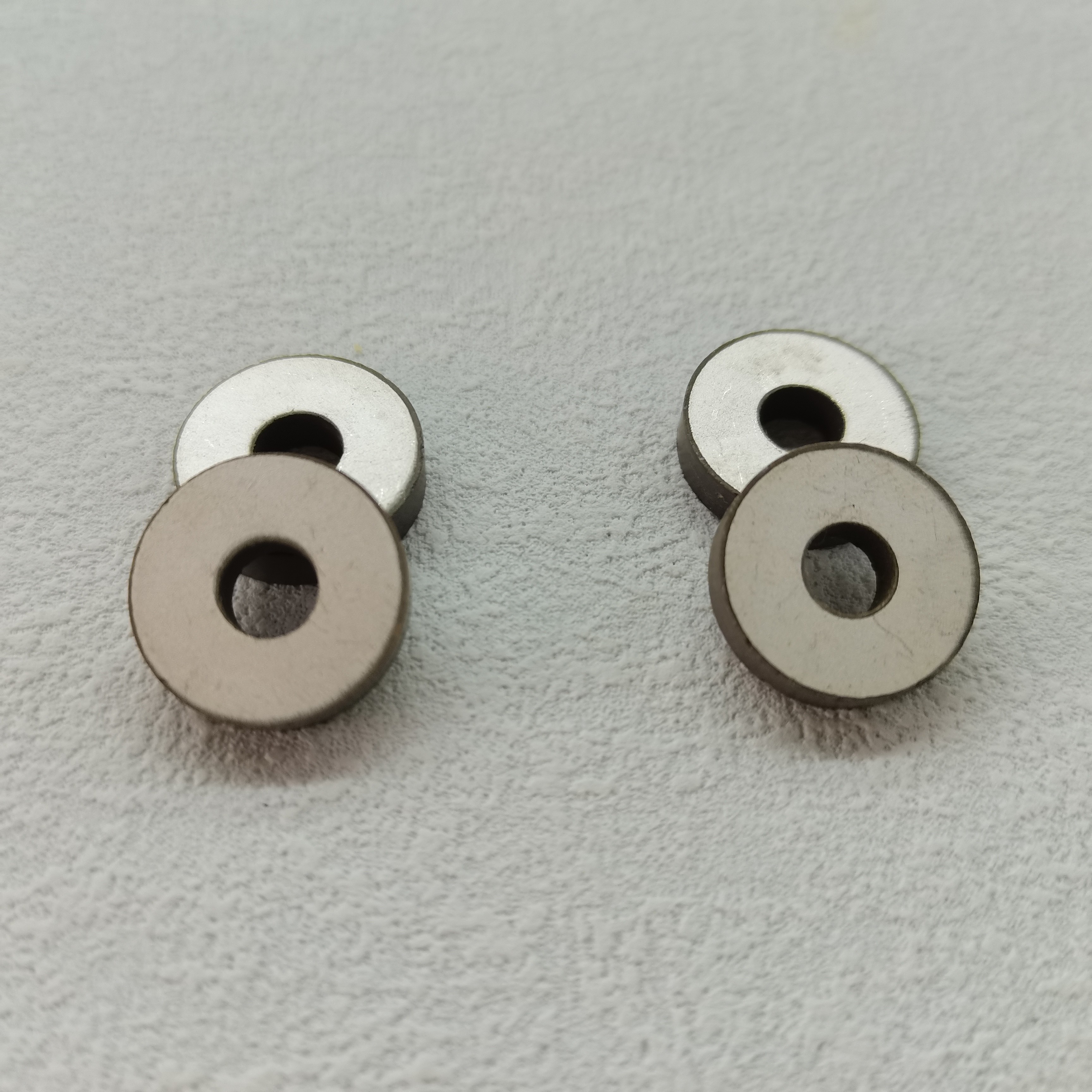
Underwater transducer arrays are rarely limited by a single material property. A piezoelectric element that looks strong on a datasheet may still create problems once it is placed inside a pressure-rated housing, connected to matching layers, driven across a useful frequency range, and exposed to years of saltwater vibration and thermal cycling. For technical evaluators, selecting Piezoelectric Composites Materials is therefore a system-level decision rather than a simple comparison of piezoelectric coefficients.
The material must support the acoustic mission of the array: transmitting efficiently, receiving weak echoes, maintaining element-to-element consistency, and operating reliably under hydrostatic pressure. It must also fit the practical realities of manufacturing, including electrode design, backing attachment, encapsulation, cable termination, and quality control across many channels.
This guide focuses on the decisions that matter when evaluating piezoelectric composite materials for sonar arrays, underwater communication equipment, hydrophones, imaging transducers, and other submerged acoustic sensing systems.
Start with the Array’s Acoustic Job, Not the Material Name
Terms such as “1–3 composite,” “PZT composite,” or “piezo ceramic composite” are useful starting points, but they do not define whether a material is appropriate for a specific project. The geometry, operating mode, frequency target, depth rating, pulse requirement, and receive sensitivity all influence the correct choice.
For example, a shallow-water imaging array may prioritize broad bandwidth and low acoustic impedance, while a deep-water projector may place greater emphasis on power handling, mechanical robustness, and reduced depoling risk. A towed array may value flexibility and low self-noise. A fixed seabed sensor may be more concerned with long-duration stability and resistance to moisture ingress.
Before comparing candidate Piezoelectric Composites Materials, define the performance envelope in measurable terms:
- Operating frequency, bandwidth, and acceptable frequency drift
- Transmit, receive, or dual-mode operation
- Required source level, receive sensitivity, and signal-to-noise margin
- Array aperture, element pitch, element count, and beamforming requirements
- Expected hydrostatic pressure and pressure-cycle profile
- Duty cycle, pulse shape, drive voltage, and thermal loading
- Housing, matching layer, backing, potting, and cable constraints
- Target operating life and environmental exposure conditions
A material review becomes much more efficient once these boundaries are clear. Without them, teams often select a composite for its high nominal sensitivity, then discover that its impedance, thermal behavior, or process tolerance complicates the final array.
Why Composite Architecture Changes Underwater Performance
Piezoelectric composites generally combine an active piezoelectric ceramic phase with a passive polymer phase. In a commonly used 1–3 architecture, ceramic rods are aligned in the polarization direction and embedded in a polymer matrix. This arrangement can preserve useful thickness-mode activity while reducing lateral constraints that are more pronounced in monolithic ceramic elements.
Compared with dense piezoelectric ceramics, composites may offer lower acoustic impedance, better compatibility with water and polymer matching layers, broader bandwidth, and reduced lateral-mode interference. These benefits are particularly attractive when a transducer needs to couple energy efficiently into water rather than reflect it at a large impedance boundary.
However, the polymer phase is not merely filler. Its stiffness, density, damping behavior, thermal expansion, moisture resistance, and bonding quality influence the finished element. Ceramic volume fraction, pillar aspect ratio, kerf width, electrode arrangement, and backing interaction all affect resonance behavior. A composite should therefore be evaluated as a designed structure, not as a generic substitute for bulk PZT.
Evaluate the Properties That Affect the Finished Transducer
Acoustic impedance and impedance matching
Water has a much lower acoustic impedance than dense piezoelectric ceramic. This mismatch can restrict energy transfer unless matching layers are carefully designed. Composite structures can lower effective acoustic impedance and make matching-layer design more manageable. In array applications, this may support broader useful bandwidth and a more controlled transmit or receive response.
Still, lower impedance is not automatically better. The optimum value depends on the front-face stack, element dimensions, operating mode, and desired bandwidth. Evaluators should request measured impedance and phase behavior from representative elements, not only nominal material values. A clean electrical resonance does not guarantee an equally clean acoustic response after assembly.
Piezoelectric activity and electromechanical coupling
Parameters such as d33, g33, dielectric permittivity, and thickness-mode coupling factor are important, but each tells only part of the story. High charge sensitivity can be valuable for receiving weak underwater echoes. Strong coupling can help achieve bandwidth and conversion efficiency. Yet a material with impressive coefficients may introduce capacitance levels or mechanical losses that make the array electronics more difficult to design.
For receive arrays, voltage sensitivity, capacitance stability, noise behavior, and channel uniformity deserve close attention. For transmit arrays, coupling, mechanical quality factor, allowable field strength, and heat generation under the real pulse schedule become more important. A dual-function sonar array needs a deliberate compromise rather than an attempt to maximize one parameter.
Mechanical quality factor and damping
The mechanical quality factor, often expressed as Qm, influences how sharply the element resonates and how readily vibration decays. A high-Q design may support strong narrowband output, but ringing can reduce range resolution or complicate pulsed operation. More damping can shorten the pulse and broaden bandwidth, although it may reduce peak efficiency.
This balance should be assessed with the actual backing and encapsulation materials. In an underwater array, the backing is part of the acoustic design. A composite that appears well damped by itself can behave differently once bonded into a stack with adhesive layers and a dense backing block.
Hydrostatic pressure response
Hydrostatic pressure changes the mechanical boundary conditions of the active element and may shift resonance, alter impedance, or reduce sensitivity. At greater depths, sustained pressure and repeated pressure cycling become central qualification concerns. The polymer matrix, ceramic-polymer interface, electrodes, and protective coatings all need to tolerate the intended environment.
Ask whether the proposed composite has been evaluated under pressure representative of the operating depth, preferably as an assembled element rather than as an unmounted coupon. Useful test evidence includes resonance shift under pressure, insulation resistance, capacitance change, receive sensitivity retention, and visual inspection for cracking, delamination, or water ingress after cycling.
Bandwith Is a Stack-Level Result
Technical discussions sometimes credit composite materials alone for broadband operation. In practice, bandwidth comes from the interaction of the active composite, front matching layers, backing, mass loading, housing window, and electrical drive conditions. A broad-band composite can still produce a narrow or irregular response if the surrounding structure is poorly matched.
For phased arrays, response consistency matters as much as individual bandwidth. Small variations in resonant frequency, phase, or sensitivity can become visible in beam patterns, especially when arrays contain many closely spaced elements. The material supplier should be able to discuss how ceramic distribution, pillar geometry, poling, electrode coverage, and dimensional control affect lot-to-lot repeatability.
When comparing options, consider requesting the following from representative samples:
- Impedance and phase curves over the relevant frequency range
- Resonance and anti-resonance frequency distribution across multiple elements
- Capacitance and dielectric loss at the intended measurement conditions
- Transmitting voltage response or receiving voltage sensitivity in a relevant acoustic setup
- Pulse response, ring-down behavior, and bandwidth after integration with a provisional stack
- Performance before and after thermal, humidity, and pressure exposure
These results provide a more realistic basis for array selection than a single material-property table.
The Ceramic Formulation Still Matters
A composite architecture does not remove the importance of the underlying piezoelectric ceramic. Different ceramic formulations are commonly chosen for their relative emphasis on sensitivity, stability, power capability, or dielectric behavior. Soft formulations may provide high piezoelectric response but can be less suitable for severe high-field transmitting conditions. Harder formulations can better tolerate power drive and mechanical stress, though usually with different sensitivity and loss characteristics.
The decision should reflect the application’s dominant mode. A passive hydrophone element, for instance, is not judged by the same criteria as a high-power underwater projector. If the array alternates between transmitting and receiving, the selected ceramic and composite geometry should be tested under both conditions rather than assumed to perform equally well in each.
Suppliers with experience in piezoelectric ceramics can be helpful during this stage because ceramic formulation, poling process, machining behavior, and composite fabrication are interconnected. Weifang Jude Electronic Co. Ltd manufactures piezoelectric ceramic components used across ultrasonic and sensing applications, including underwater sound and sonar-related uses. For an array program, the most productive supplier discussion is usually not “Which material is best?” but “Which material and structure best fit this acoustic stack, operating environment, and production tolerance?”
Array Manufacturing Risks Often Appear at the Interfaces
A successful prototype does not always translate into reliable multi-element production. Composite materials introduce interfaces between ceramic, polymer, adhesive, electrode, matching layer, backing, and encapsulant. Each interface can influence yield and lifetime.
One recurring concern is coefficient of thermal expansion mismatch. Ceramic and polymer respond differently to temperature changes, while the surrounding housing and backing may add further stress. Repeated thermal cycles can fatigue bonds, change preload, or create microcracks that are difficult to detect before acoustic performance declines.
Another concern is moisture management. Even if the external package is designed for immersion, moisture can reach vulnerable paths through imperfect seals, cable transitions, or damaged coatings. The chosen polymer system, edge sealing method, and electrode protection should be reviewed together. It is not enough to state that an active composite is “water resistant” without defining the full sealing approach.
For fine-pitch arrays, dimensional tolerances also become an acoustic issue. Variations in pillar alignment, kerf fill, thickness, electrode placement, or dicing quality can affect cross-talk and channel balance. This is especially relevant for imaging arrays, where unwanted lateral modes and acoustic cross-coupling may degrade contrast or complicate calibration.
A Practical Selection Sequence for Technical Evaluators
A disciplined evaluation usually moves from broad screening to integrated verification. Begin by separating non-negotiable requirements from optimization targets. Maximum operating depth, frequency range, element geometry, and drive condition are often non-negotiable. Bandwidth, sensitivity, cost, processing convenience, and lead-time considerations may be optimization targets, depending on the project.
Next, compare two or three candidate material architectures rather than reviewing a long list of unrelated grades. Build simple models of acoustic impedance, resonant behavior, and matching-layer interaction, then validate assumptions with sample elements. The first samples should be made in dimensions close to the intended design; generic discs or bars are useful for initial screening but cannot fully represent a narrow array element.
After bench characterization, test assembled subarrays in water. This step reveals practical issues such as channel variation, cross-talk, cable loading, beam steering behavior, and packaging effects. If deep-water deployment is expected, conduct pressure exposure before finalizing the design. A material that meets initial acoustic targets but shifts excessively after pressure cycling is not a low-risk selection.
Finally, assess supply consistency. Ask about raw material control, inspection methods, available dimensions, machining limits, polarization capability, and how changes between batches are communicated. For arrays, predictable variation is often more valuable than an isolated peak-performance sample.
Questions Worth Asking a Piezoelectric Composite Supplier
Supplier conversations become more useful when questions are tied to the actual design. Technical evaluators may ask:
- Which composite connectivity and ceramic formulation are recommended for this frequency, depth, and transmit/receive duty?
- What ceramic volume fraction and pillar geometry are feasible at the required element pitch?
- Which material properties are measured on finished composite parts, and at what test conditions?
- How are resonance consistency, capacitance, dielectric loss, and polarization verified?
- What limitations apply to dicing, electrode patterning, bonding, and encapsulation?
- Can samples be supplied in geometry representative of the proposed array?
- What environmental tests are appropriate before moving from prototype to production?
The answers help distinguish a material supplier that can support application development from one that provides only nominal property data.
Make the Final Decision Around Stable Field Performance
The right Piezoelectric Composites Materials for an underwater transducer array are not necessarily those with the highest published coefficient or the lowest acoustic impedance. The stronger choice is the one that delivers the required acoustic response after being integrated into the real transducer stack, remains stable under pressure and temperature exposure, and can be manufactured with repeatable channel performance.
For technical evaluators, that means looking beyond individual values and asking how the composite behaves as part of an acoustic system. When material architecture, ceramic formulation, matching design, environmental protection, and production control are considered together, the result is a more defensible selection—and a lower chance of discovering expensive limitations after the array has already moved into qualification.

Thank you very much for writing to us. Please leave your message and contact information, we will reply to you within 24 hours.