

Integrating High-Power Piezoelectric Ceramic Rings into Ultrasonic Welding Stacks
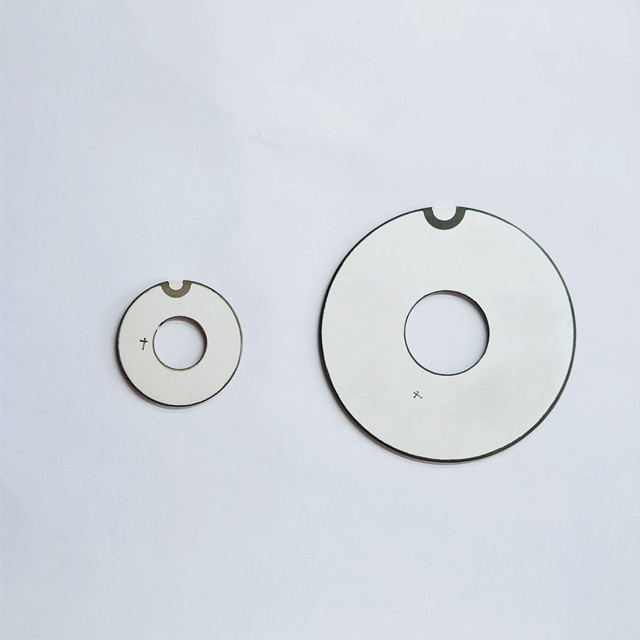
Integrating High-Power Piezoelectric Ceramic Rings into Ultrasonic Welding Stacks
Integrating high power piezoelectric ceramic components into ultrasonic welding stacks requires more than selecting rings with the right dimensions. Reliable performance depends on aligning material properties, electrode configuration, preload, and resonance with the demands of the complete assembly. Poor integration can contribute to overheating, unstable amplitude, and costly commissioning delays. The practical challenge is to define what the ceramics must do inside the stack—and establish how the assembled system will be validated before production.
Start with the welding duty, not the ring drawing
A ring that fits an existing transducer is not necessarily a suitable replacement. Two ceramics can share the same dimensions and nominal capacitance yet behave differently under high excitation. Material losses, coupling, temperature sensitivity, and mechanical consistency all affect the operating result.
Before requesting samples, define the intended operating frequency, generator tracking range, weld amplitude, cycle duration, repetition rate, and cooling arrangement. Include the booster and horn configuration. A transducer operating intermittently on a development bench faces a different thermal duty from one running repeated welds inside an enclosed production machine.
Also clarify where amplitude is specified. Horn-tip displacement is not ceramic displacement; the mechanical gain between them matters. Specifying only generator power leaves too much unresolved because actual ceramic stress depends on the complete resonant assembly and its load.
Select material for power operation, then check the trade-offs
Hard PZT formulations are commonly considered for ultrasonic welding because their relatively low losses and high mechanical quality factor suit resonant power operation. That does not make the formulation with the highest published quality factor automatically the best choice. Coupling, allowable drive conditions, thermal behavior, and the generator’s ability to follow resonance still need consideration.
Treat low-signal datasheet values as screening information, not proof of performance at welding amplitude. Ask how the supplier measured capacitance, dielectric loss, resonance, and coupling, including temperature and test conditions. Where high-drive characterization is unavailable, allow for application testing rather than assuming small-signal values remain unchanged.
The Curie temperature is not a permissible operating-temperature rating. The usable limit must account for depoling risk, electrodes, insulation, bonding materials where present, and changes in performance with temperature. Obtain an application-specific temperature limit and an agreed measurement location.
Weifang Jude Electronic Co. Ltd supplies piezoelectric ceramics and power transducers for applications including ultrasonic welding, cleaning, and sensing. For a welding project, the useful discussion is application-specific: which material, ring tolerances, and inspection conditions can be supplied consistently? Experience across piezoelectric applications provides context, but sensing-grade specifications should not be carried into a power stack without review.
Resolve preload and contact quality together
In a bolt-clamped transducer, preload keeps the ceramic interfaces compressed during vibration. Insufficient compression can allow interface separation, localized heating, and damaging tensile stress. Excessive or uneven compression can also damage the rings or alter their behavior. There is no universal tightening torque that safely covers different ring sizes, bolts, materials, and contact conditions.
Torque is an indirect way to control clamping force because thread and bearing-surface friction affect the result. If torque-controlled assembly is used, define lubrication, washer arrangement, tightening sequence, and tool calibration. For more demanding assemblies, consider a validated bolt-elongation or other preload-verification method.
Contact geometry deserves equal attention. Ring-face flatness and parallelism, electrode thickness, and mass-face condition determine how evenly compression is distributed. A burr or trapped particle can concentrate stress even when the recorded tightening torque is correct. Define cleaning and inspection requirements before assembly becomes a production task.
Thermal expansion can change preload during operation. Review the bolt, front mass, rear mass, and ceramic stack as a mechanical system, rather than treating the bolt as ordinary fastening hardware. Any planned retightening or conditioning procedure should be validated, not improvised after an assembly runs hot.
Make polarity and insulation unambiguous
Many welding transducers use axially poled rings arranged mechanically in series and electrically in parallel. Ring orientation and electrode connections must ensure that the driven strains reinforce one another. A polarity error may leave an apparently complete assembly with weak output or abnormal electrical behavior.
Require an assembly drawing showing poling direction, electrode sequence, terminal routing, and bolt insulation. Do not rely on an informal rule such as “alternate the rings” without defining the corresponding connections. Polarity markings must remain traceable through receiving inspection and assembly.
Electrode tabs and leads also need mechanical consideration. Unsupported connections can fatigue under vibration; poorly routed wiring can rub against metalwork or compromise clearance. Check insulation resistance using an agreed procedure, and ensure any dielectric withstand test is appropriate for the assembled design.
Tune the assembly that will actually weld
A ceramic ring’s resonance is not the operating resonance of the finished welding stack. The masses, bolt, interfaces, booster, and horn all influence the assembled modes. Changing ceramic grade or stack height can therefore require more than a generator setting adjustment.
Use impedance analysis to identify the intended longitudinal mode and nearby unwanted modes. Check the transducer separately, then repeat measurements with the intended booster and horn. A satisfactory room-temperature frequency reading does not establish acceptable behavior under load or after heating.
If amplitude falls while current and temperature rise, increasing generator output is not a sound first response. Possible causes include detuning, interface loss, incorrect preload, a damaged ceramic, or a tooling problem. Diagnose the mechanical and electrical assembly before applying more drive.
Set acceptance criteria before commissioning
A practical validation plan should distinguish incoming ceramic quality from assembled-stack performance. Otherwise, a failed weld trial can turn into an inconclusive debate between the ceramic supplier, transducer builder, and tooling team.
- Incoming rings: inspect dimensions, face condition, polarity identification, and agreed electrical characteristics under defined conditions.
- Assembled transducer: record preload method, impedance response, insulation results, and low-drive vibration behavior.
- Complete welding stack: verify amplitude, tracking stability, and temperature rise using the intended tooling and representative duty cycle.
- After endurance testing: compare electrical and mechanical measurements with the initial baseline, and investigate drift before release.
Keep weld quality in the acceptance plan, too. Stable resonance alone does not prove a satisfactory joint; fixture support, contact force, part geometry, and material variation remain relevant. Assign ownership of these checks before ordering production quantities. The decision to release high power piezoelectric ceramic components should rest on repeatable performance in the intended stack—not simply a dimensional match or a successful no-load demonstration.

Thank you very much for writing to us. Please leave your message and contact information, we will reply to you within 24 hours.