

Moisture Delamination Is Usually a System Failure, Not a Surface Defect
Delamination in piezoelectric composite materials deserves attention as soon as there is evidence of reduced output, unstable impedance, drift in sensitivity, unexplained heating, or intermittent operation after storage or washdown exposure. Once moisture reaches an interface, the loss of adhesion can spread under thermal cycling, vibration, or high-voltage excitation. A transducer may still operate during a bench check while becoming unreliable in service.
For after-sales maintenance teams, the practical question is rarely whether water can damage a piezoelectric assembly. It can. The more useful question is where moisture entered, what interface it affected, and whether the assembly can still be returned to service without creating a repeat failure.
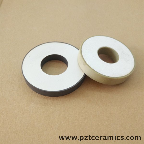
Piezoelectric Composites Materials often combine ceramic elements with polymer matrices, electrodes, matching layers, backing materials, adhesives, cable terminations, and protective housings. Each interface has a different response to humidity, liquid exposure, temperature change, and mechanical stress. Moisture-driven delamination is therefore not limited to one material defect or one sealing mistake. It is often the visible result of several small weaknesses acting together.
Why Moisture Causes Delamination Before It Causes an Obvious Electrical Failure
Moisture can enter an assembly through damaged external coatings, incomplete potting, cracked cable jackets, weak connector seals, poorly bonded housings, or microscopic gaps at bonded interfaces. Liquid immersion is an obvious threat, but repeated condensation can be just as damaging. Equipment that moves between cold storage, warm processing areas, outdoor environments, or washdown zones can experience condensation inside spaces that appear sealed from the outside.
After ingress, several failure mechanisms can occur at the same time. A polymer adhesive or matrix may absorb water and swell. The ceramic, metal electrode, and housing generally expand differently from the polymer layer. That mismatch places shear stress along the bond line. Repeated wetting and drying can then weaken the interface even where there is no visible crack.
Moisture also changes electrical conditions. It can lower insulation resistance, create leakage paths around electrodes, promote corrosion of conductive surfaces, and alter the dielectric response of the assembly. In ultrasonic equipment, these changes may appear as reduced amplitude, unstable resonance, altered power demand, or abnormal heat generation. In sensing equipment, they may show up as baseline drift, lower signal-to-noise ratio, poor repeatability, or sporadic output.
The defect may be localized. A small region of bond separation can change how vibration is transmitted through a stack or composite structure. That is why a unit with acceptable continuity readings can still perform poorly under its actual operating frequency, load, and temperature.
Separate External Water Exposure From Internal Moisture Retention
Maintenance teams often focus on the event that made water visible: a washdown cycle, rain exposure, leaking process line, or accidental immersion. That event matters, but it does not always identify the root cause. In many cases, water reaches a vulnerable interface because the assembly retained moisture from an earlier exposure or because a seal had already degraded.
A useful first distinction is between external wetting and internal retention.
- External wetting affects the housing, connector, cable exit, exposed coating, or mounting surface. It may be resolved if the protective boundary is intact and moisture did not pass beyond it.
- Internal retention occurs when water enters potting compounds, porous backing materials, adhesive edges, cable strain-relief regions, or interface gaps. Drying the exterior does not necessarily remove moisture trapped inside the assembly.
Internal retention is especially important after a unit has been exposed to liquid and then returned quickly to operation. Heating can drive moisture deeper into porous or imperfectly bonded regions. Electrical excitation may then accelerate corrosion and interface stress. A fast functional check immediately after drying may produce a misleading result because the failure mechanism has not yet fully developed.
For service decisions, treat a moisture event as more serious when the unit has experienced pressure washing, prolonged immersion, repeated condensation, process chemicals, salt-bearing water, elevated temperature, or vibration while wet. These conditions increase the likelihood that moisture has bypassed the intended barrier and affected the active structure.
Early Signs That Point to Delamination Rather Than a Simple Wiring Fault
A damaged cable, loose connector, or failed power supply can produce symptoms similar to moisture-related delamination. The difference is often found by comparing electrical checks with mechanical and process history.
Visual inspection matters, but it should not be the only basis for release. A perfectly clean exterior does not prove that the ceramic-polymer interface, matching layer, backing layer, or internal electrode region is intact. Conversely, surface staining alone does not prove delamination. The maintenance task is to connect the physical evidence with changes in electrical and acoustic performance.
Inspect in the Order Moisture Is Likely to Travel
Inspection is more effective when it follows likely ingress paths rather than starting at the piezoelectric element itself. Begin with the points where the protective boundary is interrupted: cable entries, connectors, fasteners, seams, mounting interfaces, vent features, sensor faces, and transitions between hard housings and soft sealants.
Look for gaps at cable strain reliefs, cracked overmolding, loose connector backshells, flattened or chemically attacked gaskets, brittle sealant, peeling coatings, and corrosion near metal-to-polymer transitions. A seal that appears continuous can still fail where it has lost adhesion at the edge.
Next, inspect the operating environment. A replacement assembly installed into the same leaking enclosure or mounted against a surface that traps liquid will repeat the failure. Check whether process fluid collects around the cable exit, whether cleaning procedures direct high-pressure water toward seams, whether mounting hardware damages a gasket, and whether temperature changes create recurring condensation.
Electrical measurements should be interpreted against the product's expected behavior. Insulation resistance, capacitance, impedance, resonance characteristics, and continuity can all be useful, but no single reading diagnoses delamination in every design. A comparison with an approved baseline, a similar unaffected unit, or the manufacturer's acceptance criteria is more meaningful than an isolated value.
For ultrasonic transducers and power assemblies, measure behavior under conditions that approximate real use where this can be done safely. A part may appear normal at low excitation but show excessive heating, poor amplitude stability, or abnormal frequency response at operating power. For sensing components, examine repeatability and drift over a suitable period rather than relying only on a single output reading.
Drying Can Be Necessary, but It Is Not a Repair Method
Controlled drying may be appropriate after limited exposure when inspection shows no compromised seal, corrosion, deformation, or performance change. It can reduce the risk of powering a wet assembly and can help distinguish surface moisture from a persistent internal defect. However, drying does not restore an adhesive interface that has already lost bond strength, and it does not reverse corrosion on internal electrodes or terminals.
A common service error is to dry a suspect unit, obtain a passing functional test, and return it to a wet or thermally demanding application without correcting the ingress route. If moisture was present at an interface, the next exposure can reopen the failure. The risk is higher where the component is subjected to high-frequency vibration, high voltage, cyclic loading, or repeated temperature changes.
Do not use uncontrolled heating that can create large temperature gradients through the piezoelectric assembly. Ceramic elements, polymer layers, adhesives, and encapsulants do not necessarily tolerate the same temperature or heating rate. Excessive heat can introduce new stresses, soften a sealant, shift a bonded layer, or damage cable insulation. Follow the component manufacturer's drying and handling limits when they are available.
When Resealing Is Reasonable and When Replacement Is the Better Decision
Resealing is reasonable only when the active structure remains stable and the defect is confined to an accessible external barrier. Examples include a damaged outer cable jacket, a degraded external gasket, a failed connector seal, or a coating defect that has not allowed meaningful internal ingress. The repair must restore adhesion to compatible, properly prepared surfaces and preserve the component's mechanical constraints.
External sealant should not be used to conceal an uncertain internal fault. Adding material over a cracked housing seam or cable exit may slow further exposure, but it cannot confirm that the internal composite has remained dry. It can also make later inspection harder and may change vibration behavior in sensitive assemblies.
Replacement becomes the more defensible choice when there is evidence of internal delamination, corrosion near active electrodes, persistent insulation loss, unstable resonance, performance drift after drying, swollen or softened potting, or repeat moisture failures from the same unit. In a critical ultrasonic welding, fault-detection, underwater acoustic, flow-measurement, or oil-well measurement application, the cost of uncertain performance can exceed the cost of replacing the piezoelectric component.
For a composite assembly, replacement should include a review of the original installation conditions. A technically sound component can still fail early if the cable route holds water, the enclosure breathes humid air, the mounting face is not flat, or a cleaning chemical attacks the selected sealant. The corrective action needs to cover both the part and the moisture path.
Prevention Starts Before Field Installation
Moisture prevention is easiest when storage, installation, and service practice are treated as part of component reliability. Piezoelectric ceramic and composite assemblies should remain in dry, protected packaging until installation. Avoid leaving unpacked parts near open wash areas, cold loading bays, process steam, or locations where they can cycle through condensation conditions.
Before fitting a replacement, inspect the mating surfaces and confirm that the housing, connector, mounting face, cable route, and enclosure drainage are suitable. Keep bond and sealing surfaces clean. Oils, cleaning residues, dust, old gasket fragments, and moisture on the surface can reduce seal adhesion even when the sealant is correctly selected.
During installation, avoid excessive clamp load, sharp cable bends, unsupported cable weight, and fastener patterns that distort the housing. Mechanical distortion can open a microscopic path at a seal edge or introduce stress into a bonded composite layer. Where a component is designed for a specified gasket, potting material, connector, or mounting arrangement, substituting a visually similar material can alter chemical resistance, flexibility, or long-term adhesion.
- Record the exposure event, including liquid type, duration, temperature, and whether the unit was energized.
- Inspect cable entries and connector seals during routine maintenance, especially after washdown or environmental incidents.
- Trend electrical or acoustic measurements when the equipment supports baseline comparison.
- Correct standing-water and condensation sources around the installed assembly.
- Quarantine units with changed performance until the condition is understood, rather than repeatedly resetting or recalibrating them.
Use Failure History to Improve the Next Service Decision
Repeated delamination complaints should be grouped by exposure pattern, not only by part number. Failures that occur after cleaning point toward sealing, chemical compatibility, or installation geometry. Failures after storage may indicate packaging, condensation, or handling conditions. Failures that develop only under sustained ultrasonic power may reveal a marginal interface that becomes unstable under heat and vibration.
That distinction helps maintenance teams avoid two costly responses: replacing a piezoelectric assembly without fixing its environment, or repeatedly resealing an assembly whose active interfaces have already been compromised. Moisture-driven delamination is best controlled by finding the first breached barrier, verifying whether internal performance has changed, and making the repair-versus-replacement decision before the equipment returns to demanding service.

Thank you very much for writing to us. Please leave your message and contact information, we will reply to you within 24 hours.