

Why does a piezo sensor produce a weak signal?
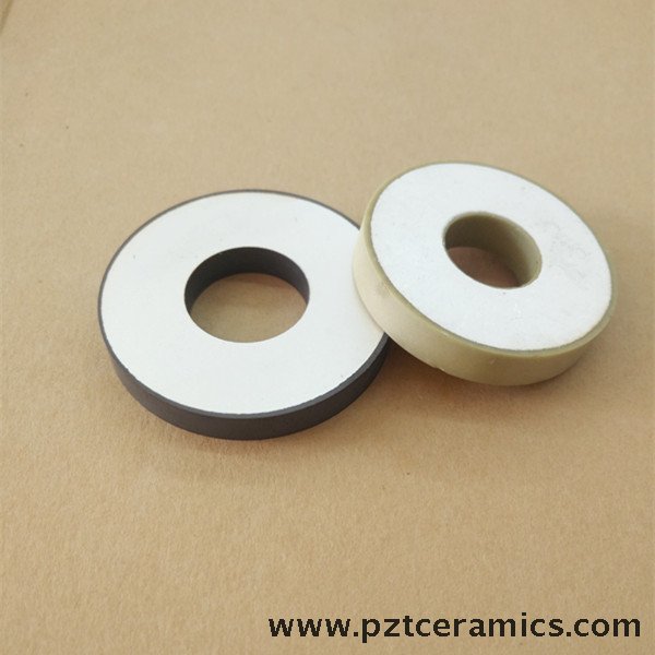
A weak Piezo Sensor signal can result from insufficient mechanical input, poor coupling, damaged wiring, moisture, an unsuitable measuring instrument, or a fault in the sensor or its signal-conditioning circuit. The quickest route to a reliable diagnosis is to check the mechanical stimulus and measurement setup before replacing the sensing element.
On operating equipment, the symptom may be a low-amplitude waveform, intermittent triggering, or readings that drift below the normal operating range. These symptoms can also come from a change in the machine itself. Compare the signal under repeatable operating conditions and trace it from the sensor toward the controller to determine where the loss occurs.
Establish what “weak” means on this equipment
Before disconnecting anything, identify the sensor’s intended function and the type of output expected. A passive piezoelectric element generates charge when its mechanical stress changes. Its output depends on the applied force, vibration, pressure variation, or other stimulus, as well as the electrical load connected to it. It is not a general-purpose static-force sensor: a sustained load may initially produce a response that then decays as charge leaks through the measurement circuit.
Other assemblies include an integrated amplifier or connect to an external charge amplifier. A low reading from an assembly with electronics can therefore reflect a supply, bias, amplifier, or configuration problem rather than a weak ceramic element. Consult the equipment documentation to establish the expected waveform, operating frequency, test point, and any normal range. Do not assume that two sensors with similar connectors have interchangeable outputs.
Record the operating state when the problem occurs: machine speed or cycle, load, temperature, cable position, and whether the signal is continuously low or only occasionally missing. A comparison with a known-good channel can be useful, provided that both channels use the same sensor type, mounting arrangement, input settings, and operating conditions. A waveform captured at a different machine speed or with a different probe setting is not a dependable baseline.
Start at the mechanical interface
A piezoelectric element can only respond to the stress reaching it. Loose fasteners, a shifted contact point, an unsuitable mounting surface, or a coupling layer that has deteriorated can reduce the energy transferred to the sensor. The electronics may be working correctly while the physical stimulus at the sensing element has changed.
Inspect the mounting according to the equipment instructions. Look for movement, contamination, damaged threads, distorted brackets, or debris trapped between contact surfaces. Restore the specified mounting method and tightening conditions; overtightening can damage a sensor or alter its response, while insufficient contact can make readings inconsistent. Where a couplant is required, use the specified material and application method rather than adding an arbitrary layer.
Also check the source of the stimulus. A lower vibration level, reduced pressure variation, altered contact force, or a change in the machine’s operating cycle may produce a legitimately smaller signal. For an ultrasonic receiver, alignment, contact pressure, couplant condition, and the transmitting path can all affect the received amplitude. Confirm the source and receiving conditions before concluding that the receiver has lost sensitivity.
When the equipment permits it, repeat the same controlled stimulus after correcting the mounting. A response that changes markedly with cable movement points in a different direction from one that changes with mounting pressure. Avoid striking a ceramic element or applying an uncontrolled load as a substitute for a defined functional test.
Check the measurement path before condemning the sensor
Passive piezoelectric elements are high-impedance sources. Connecting one directly to an instrument with insufficient input impedance can drain charge and make the displayed voltage appear weak, particularly at lower frequencies. A probe can also add capacitance; together with cable capacitance and the element’s own capacitance, it changes the voltage observed at the input. The measurement may be loading the very signal being investigated.
Use the specified high-input-impedance instrument, preamplifier, or charge amplifier, and follow the manufacturer’s connection instructions. A charge amplifier is often used to convert sensor charge into a usable voltage, but its range, sensitivity, time constant, and frequency response must suit the application. Confirm the oscilloscope probe attenuation setting matches the instrument setting, and check bandwidth limits, filters, gain, and scaling in the acquisition software.
Cable length and type matter as well. A replacement cable with different capacitance or insulation characteristics can alter a voltage-mode measurement. Long, moving, or damaged cables may introduce noise or leakage. Use the specified cable and keep the cable configuration consistent when comparing channels. Do not infer that a sensor is defective solely because its open-circuit voltage differs between two instruments.
Follow the signal through accessible test points
- Observe the output at the designated downstream test point under a repeatable operating condition. Record amplitude, waveform shape, frequency content, and whether the signal is stable.
- Check the sensor connector and cable for loose contacts, bent pins, damaged insulation, moisture, and strain at the entry point. Move the cable gently only where it is safe and permitted; an intermittent change can help locate a break or poor connection.
- Where the design provides a safe, specified upstream test point, compare the signal before and after the cable or conditioning stage using suitable instruments. Disconnecting a high-impedance sensor or changing the load can itself change the reading, so interpret the comparison in light of the circuit.
- For powered conditioning circuits, verify the specified supply, bias, grounding arrangement, and input configuration. A missing supply or incorrect channel setting may resemble a weak sensor.
- Repeat the operating test after correcting one suspected fault at a time. This makes it easier to identify the cause and avoids masking an intermittent defect.
Use the machine’s isolation and discharge procedures before opening connectors or handling circuitry. Some piezoelectric elements can generate hazardous voltages when mechanically stressed, and associated ultrasonic equipment can contain high-voltage drive circuits. Do not connect ordinary test equipment to an unknown live circuit without confirming ratings, grounding, and the prescribed test method.
Separate signal loss from noise and leakage
Electrical interference does not always make a waveform look larger. Noise can obscure the useful component, trigger the wrong threshold, or force filtering that suppresses part of the desired signal. Compare the waveform with nearby motors, drives, or switching equipment operating and stopped, where the machine procedure allows. Look for interference correlated with switching events rather than with the expected mechanical stimulus.
Inspect shielding and cable routing against the equipment design. A shield disconnected at the intended termination, a cable run close to power wiring, or an unintended ground path can introduce interference. Do not add ground connections indiscriminately: the correct shield termination depends on the circuit, and an additional connection can create another noise path.
Moisture and surface contamination are especially relevant to high-impedance inputs. They can create leakage paths across connectors, terminals, or exposed insulating surfaces, causing charge to dissipate before it reaches the amplifier. Inspect for condensation, residue, and damaged seals. Clean and dry parts only by an approved method, then address the source of ingress; restoring the reading temporarily without repairing a seal may leave the fault ready to return.
An insulation or continuity test can help locate a cable fault when the manufacturer permits it, but disconnect sensitive electronics first and use only the prescribed test voltage. Insulation testers and resistance meters are not substitutes for a functional sensitivity test, and an inappropriate test voltage can damage components.
When the sensing element may be damaged
After the stimulus, mounting, cable, and conditioning path have been checked, inspect the sensor assembly for cracks, crushed areas, corrosion, loose electrodes, or damage at the cable exit. Piezoelectric ceramics are brittle, and excessive force, impact, unsuitable clamping, or thermal exposure outside the specified range can affect performance. Some faults are internal and will not be visible.
Capacitance or insulation measurements may be useful screening checks if the sensor manufacturer provides a procedure and acceptance limits. A value within range does not prove that mechanical sensitivity is correct, and a value outside range should be interpreted with the cable, fixture, temperature, and instrument settings taken into account. Do not apply a generic capacitance limit to an unidentified element.
A controlled substitution can provide stronger evidence. Replace the suspect unit temporarily with a verified compatible sensor, using the same mounting, cable arrangement, conditioning settings, and repeatable stimulus. If the response returns to the expected range, the original sensor becomes a stronger suspect. If it does not, continue investigating the shared mechanical and electrical path. A replacement must match the required operating mode, dimensions, sensitivity, frequency response, environmental limits, and interface—not merely fit the mounting hole.
Confirm the repair under operating conditions
After repair or replacement, check more than the peak amplitude. Confirm that the waveform occurs at the expected point in the machine cycle, that it remains stable through normal operating variations, and that the controller interprets it correctly. Verify any alarm threshold, gain, or calibration setting that was changed during diagnosis; leaving a temporary gain increase in place can conceal an unresolved loss or create false triggers.
Record the final mounting condition, cable routing, instrument settings, test point, and operating state alongside the measured response. These details make a later comparison meaningful. When the output remains low despite a repeatable stimulus and verified signal path, use the equipment maker’s sensitivity test or arrange further evaluation of the sensor and conditioning electronics rather than increasing gain without a known reference.

Thank you very much for writing to us. Please leave your message and contact information, we will reply to you within 24 hours.