

How to choose a piezo sensor for impact detection
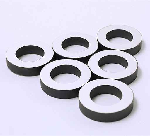
Choosing the right Piezo Sensor for impact detection requires more than comparing sensitivity ratings. Impact force, frequency response, mounting method, output voltage, and operating conditions all influence how reliably a sensor captures transient events.
For technical evaluators, understanding these factors is essential to distinguish meaningful impacts from background vibration and select a component that integrates with the signal-conditioning circuit.
The best choice is the sensor and measurement chain that detect the smallest relevant impact without saturating during the largest one, while remaining reliable after installation.
Start With the Impact You Need to Detect
Define the event before selecting a component. A sensor intended to detect occasional package drops may have different requirements from one monitoring repeated tool strikes.
Describe the impacted object, impact locations, expected contact materials, and the range of event strengths. Note whether you need detection, classification, force measurement, or impact location.
A simple detection system may only need to identify whether an event occurred. Quantitative force measurement requires a calibrated mechanical arrangement and a more carefully characterized signal chain.
Record the shortest event duration and the interval between impacts. These determine the required measurement bandwidth, sampling rate, and how quickly the electronics must recover.
Also identify non-impact events that could trigger the system, such as motor vibration, handling, cable movement, or structural resonance. These are part of the selection problem.
When force or acceleration ranges are unknown, collect representative data with a reference instrument. Estimating requirements from a supplier's sensitivity specification alone can produce misleading results.
Choose the Right Piezo Sensor Format
Piezoelectric sensing elements generate electrical charge when mechanically stressed. Available formats include ceramic discs, plates, rings, films, and packaged sensors with defined mounting interfaces.
Bare ceramic discs and plates can be compact and economical for detecting bending or transmitted vibration. Their output depends strongly on support, bonding, loading, and electrode configuration.
Ring elements can be useful in mechanically preloaded assemblies, while piezoelectric films offer flexibility and can conform to some curved surfaces. Each format needs application-specific validation.
Packaged piezoelectric accelerometers provide a more defined mechanical interface and commonly include calibration data. Some contain integrated electronics, which impose their own power and temperature requirements.
For direct force measurement, consider a purpose-designed force sensor with suitable preload and calibration. A bonded ceramic element on a machine surface does not automatically measure impact force.
Choose a bare component when your team can control mechanical design, protection, and calibration. Choose a packaged sensor when traceability and a defined installation are more important.
Match Sensitivity and Measurement Range
Sensitivity describes the electrical response to a specified mechanical input, but its units matter. Depending on the device, specifications may use picocoulombs per newton or millivolts per acceleration unit.
Only compare values measured under compatible conditions. A charge sensitivity for a force sensor cannot be directly compared with the voltage sensitivity of an accelerometer.
For a characterized force sensor, estimate charge from its stated sensitivity and expected force. Then check whether the amplifier produces a usable signal across the intended range.
For example, a sensor rated at 10 pC/N would ideally generate 100 pC under a 10 N input, assuming the calibration applies to the loading arrangement.
With an ideal charge amplifier using a 1 nF feedback capacitor, that charge corresponds to an output magnitude of approximately 0.1 V. Actual behavior depends on circuit limits.
Repeat the calculation for both the smallest meaningful event and the largest credible impact. The first must exceed noise; the second must not overload the sensor or electronics.
Include manufacturing variation, mounting differences, temperature effects, and measurement uncertainty in the margin. Confirm maximum force, acceleration, and mechanical stress ratings separately from electrical output limits.
High sensitivity is not always preferable. A highly sensitive installation may amplify unwanted structural vibration or exceed the input range during severe impacts.
Check Frequency Response Against the Event
Impacts are transient events containing energy across a range of frequencies. Shorter, sharper contacts generally contain more high-frequency content than longer, softer contacts.
Use representative waveforms or measurements to determine the bandwidth needed for the task. Detecting an event may require less bandwidth than preserving its peak and detailed shape.
Review the complete chain, including sensor, mounting, amplifier, filters, and data acquisition. Its combined response determines which parts of the impact signal reach the processor.
Pay particular attention to resonance. A sensor or mounting resonance can amplify and prolong a transient, making peak amplitude or impact duration difficult to interpret.
Choose a usable operating band supported by the sensor specification and validate it in the installed assembly. A resonant peak is not necessarily useful measurement bandwidth.
Sampling must also support the selected bandwidth. Apply suitable analog anti-alias filtering before digitization, and use a sampling rate comfortably above twice the highest retained frequency.
If accurate peak timing or waveform shape matters, substantially higher sampling rates may be needed. Verify the choice by comparing captured events at progressively higher rates.
Plan the Signal-Conditioning Circuit Early
A piezoelectric element is a charge source with capacitance and leakage effects. Its voltage response depends on sensor capacitance, cable capacitance, and the input circuit.
A high-impedance voltage amplifier is one option for short cable runs and applications where the complete input capacitance is controlled. Cable changes can alter the measured voltage.
A charge amplifier converts input charge into voltage primarily through its feedback capacitance. It can reduce sensitivity to input capacitance within the amplifier's specified operating limits.
Both approaches require attention to leakage, bias currents, shielding, grounding, and input protection. Long or moving cables may introduce noise and should be evaluated in place.
Piezoelectric sensing is generally unsuitable for steady static force measurement because charge leaks away over time. The circuit's low-frequency response also affects long-duration impacts and recovery.
Check the amplifier's input voltage and charge limits, output swing, bandwidth, and recovery after overload. Large impacts can produce voltage transients capable of damaging unprotected inputs.
Use protection components selected for the expected transient and input impedance. Their leakage and capacitance must be included in testing because they can change the measurement.
If using an integrated-electronics accelerometer, verify its required excitation, output bias, load, and interface compatibility. Do not connect it as though it were a bare ceramic element.
Make Mounting Part of the Specification
The mounting method controls how mechanical energy reaches the sensing element. A well-matched sensor can still perform poorly when adhesive, preload, or surface preparation varies.
For bonded elements, specify the bond area, adhesive type, thickness, curing process, and surface preparation. Changes in the bond can affect coupling and long-term stability.
For mechanically clamped or stud-mounted sensors, follow the manufacturer's torque and surface requirements. Excessive preload can damage components; insufficient preload can produce inconsistent contact.
Location matters as much as attachment. A sensor near a structural node may see little response at a particular frequency, even when impacts occur nearby.
Test several candidate positions using the actual structure and representative impact locations. Check whether the selected position remains effective when the impact direction or contact point changes.
Route and secure cables to limit motion-induced signals and strain on electrodes or connectors. Protect exposed ceramics from bending, moisture, abrasion, and accidental electrical contact.
Separate Real Impacts From Background Vibration
A reliable detection threshold must sit above normal background activity while remaining below the smallest impact that matters. Establish both levels with measurements, not assumptions.
Collect baseline data across operating speeds, temperatures, and operating states. Include startup, shutdown, normal handling, and other conditions likely to create false triggers.
Then introduce representative impacts at different locations and strengths. Compare peak amplitude, frequency content, duration, and repeatability with the baseline data.
Filtering can suppress irrelevant frequencies, but aggressive filtering may also remove useful impact energy or distort the waveform. Validate the full detection algorithm against recorded events.
Depending on the application, detection may use a threshold, an energy window, or multiple features. Define a minimum separation time if sensor ringing creates duplicate triggers.
Set acceptance criteria for missed events and false alarms before comparing candidates. A sensor with a larger output is not necessarily the one with better detection performance.
Verify Environmental and Production Requirements
Check operating and storage temperatures for the ceramic, adhesive, cable, connector, and electronics. The allowable system range is limited by the least tolerant component.
Review humidity, chemical exposure, dust, ingress protection, shock, and sustained vibration. A bare ceramic component may require an enclosure or coating suited to the environment.
Consider the effect of thermal cycling and aging on the bond and electrical connection. Repeated impacts can also change mounting integrity before the sensor itself fails.
For production, specify incoming inspection, dimensional tolerances, electrode configuration, capacitance, insulation characteristics, and any required sensitivity testing. Agree on test conditions and acceptance limits with the supplier.
Ask how material and process variation are controlled, and whether representative samples and technical data are available. Do not assume a custom component has standardized calibration.
Weifang Jude Electronic supplies piezoelectric ceramic components and sensors for a range of applications. For impact detection, provide the intended loading, mounting, environment, and circuit requirements when requesting support.
Use a Practical Selection and Validation Checklist
Before approving a Piezo Sensor, document the required outcome: event detection, relative severity, or calibrated measurement. Each outcome requires a different level of verification.
Shortlist candidates against mechanical limits, relevant sensitivity, usable bandwidth, temperature range, mounting constraints, and electrical interface. Reject devices with incompatible ratings before comparing cost.
Build prototypes using production-representative mounting and cables. Measure the smallest and largest expected events, background conditions, overload recovery, and variation between assemblies.
For quantitative measurements, calibrate the installed system against a suitable reference across the required range. Verify uncertainty and repeatability rather than relying only on nominal sensor sensitivity.
Finally, test durability under representative environmental exposure and repeated impacts. Record the detection threshold or calibration method so the approved design can be reproduced.
Conclusion
Selecting a piezo sensor for impact detection is a system decision: mechanical coupling, bandwidth, signal conditioning, and environmental stability matter alongside the sensing element.
Define the event and acceptance criteria first, then validate the complete installation. The right choice detects meaningful impacts consistently without unacceptable false alarms, overload, or mounting sensitivity.

Thank you very much for writing to us. Please leave your message and contact information, we will reply to you within 24 hours.