

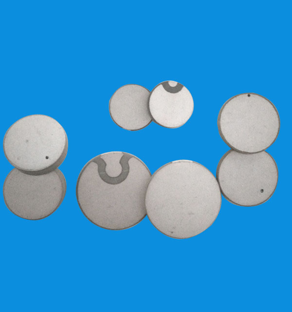
Why Failure Risk in PZT Piezoelectric Ceramics Depends on the Real Application
Common failure risks in pzt piezoelectric ceramics rarely appear for one reason alone.
In service work, the same material can behave very differently in welding equipment, flow measurement, fault detection, or underwater acoustic systems.
That is why failure analysis should start from operating conditions, not from the damaged part alone.
Depolarization, cracking, moisture ingress, insulation decline, and overload damage all reduce output stability.
But the inspection priority changes with duty cycle, temperature rise, mounting stress, drive method, and environmental exposure.
For companies working across ultrasonic, sensing, and power transducer applications, this distinction matters in daily maintenance.
Weifang Jude Electronic Co. Ltd serves a wide range of piezoelectric uses, from high frequency components to ultrasonic welding, flow meters, sonar, and sensitive fault detection.
In those settings, reliable pzt piezoelectric ceramics are judged less by a single catalog value and more by how consistently they survive the actual load pattern.
Actual Field Conditions Usually Explain the First Signs of Failure
A weak signal, unstable resonance, or rising current often appears before visible damage.
In pzt piezoelectric ceramics, these early signs usually point to stress accumulation inside the ceramic, electrode interface, or bonded stack.
More importantly, the same symptom may come from different causes.
A falling output in a high-power transducer may indicate heat-driven depolarization.
The same falling output in a sensor may come from moisture penetration or cable-side insulation leakage.
A useful maintenance habit is to separate electrical symptoms from structural symptoms before replacing the ceramic element.
High-Power Ultrasonic Systems Usually Fail from Heat and Stress Together
In ultrasonic welding, cleaning, punching, and similar power applications, pzt piezoelectric ceramics work under continuous vibration and concentrated mechanical load.
This is where after-sales teams often find the most dramatic failures.
The usual pattern is gradual heating, then reduced amplitude, then a visible crack or complete loss of efficiency.
If preload is uneven, local stress rises even when average power looks acceptable.
If resonance drifts and the driver keeps forcing the stack, depolarization can appear before anyone notices a thermal alarm.
In these systems, judging failure only by ceramic grade is usually incomplete.
It is more useful to review horn matching, bolt torque consistency, cooling path, and actual duty cycle.
- Check whether casing temperature rises faster than normal during the same workload.
- Compare impedance data before and after prolonged operation, not only at room temperature.
- Inspect stack compression surfaces for uneven contact or fretting marks.
- Confirm that the control system is tracking the real resonant point under load.
These checks often reveal why pzt piezoelectric ceramics fail earlier in one machine line than in another using the same nominal part.
Precision Sensing Applications Tend to Expose Drift Before Breakage
Length measurement, fault detection, and flow monitoring place a different demand on pzt piezoelectric ceramics.
Here, catastrophic fracture is not always the first issue.
What causes service trouble more often is signal drift, sensitivity loss, poor repeatability, or a rising noise floor.
This happens because sensor applications are more vulnerable to small changes in dielectric behavior, bonding quality, and environmental sealing.
A flow instrument, for example, may still respond, yet its measurement confidence drops long before the ceramic is physically damaged.
That is one reason components such as the ultrasonic insertion flow sensor depend on stable acoustic transmission as much as on initial sensitivity.
In this kind of service, pzt piezoelectric ceramics should be reviewed with attention to sealing, cable strain relief, temperature cycling, and medium compatibility.
The failure may be slow, but its effect on system decisions can be immediate.
What usually deserves closer attention
- Baseline capacitance drift after seasonal humidity change.
- Output inconsistency between identical channels in the same instrument.
- Encapsulation aging near edges, feedthroughs, or bonding joints.
- Signal degradation after cleaning fluids or process media exposure.
Harsh Outdoor and Submerged Use Brings Different Risks Than Indoor Equipment
Oil well measurement, underwater sound, sonar, and exposed flow systems add another layer of failure risk for pzt piezoelectric ceramics.
Mechanical output still matters, but environmental attack becomes part of the main picture.
Moisture ingress is the obvious concern, yet pressure fluctuation, thermal shock, and corrosion around electrodes can be just as damaging.
In submerged or field-mounted assemblies, small sealing defects often stay hidden until acoustic performance has already shifted.
That makes routine insulation testing and trend comparison more valuable than waiting for a total fault.
Where a design includes an ultrasonic insertion flow sensor, the surrounding pipe conditions, vibration, and medium temperature can influence ceramic life as much as the transducer structure itself.
This is a common point of misjudgment in pzt piezoelectric ceramics maintenance.
Different Scenarios Change What Good Inspection Looks Like
The practical difference between applications can be summarized in the inspection focus.
Using one checklist for every device usually leaves blind spots.
This is also why experienced suppliers place value on product coherence, process control, and application fit.
When pzt piezoelectric ceramics are used across many electrical functions, consistent manufacturing helps, but field reliability still depends on correct matching.
Common Misjudgments That Shorten Service Life
Several mistakes appear repeatedly when pzt piezoelectric ceramics fail earlier than expected.
- Treating similar frequency ratings as proof that two applications have the same load condition.
- Checking only the ceramic element while ignoring driver waveform and mounting stress.
- Assuming a dry factory test predicts long-term behavior in humid or submerged service.
- Focusing on replacement cost while overlooking calibration loss, downtime, and repeat disassembly.
- Using room-temperature test data to judge equipment that normally runs with constant heat rise.
These are not minor details.
In many systems, they determine whether pzt piezoelectric ceramics age gradually and predictably, or fail in a way that interrupts the whole instrument.
A More Reliable Way to Judge Fit Before Failure Returns
When a replacement or redesign is being considered, the first step is to map the real operating window.
That means voltage, frequency shift, duty cycle, clamping condition, ambient humidity, and the medium around the transducer.
Next, compare old and new parts under those same conditions instead of relying on nominal specifications alone.
For pzt piezoelectric ceramics, this approach is usually more effective than replacing units one by one after each failure.
It also helps clarify whether the issue comes from material selection, assembly design, or service environment.
A practical follow-up is to build a simple inspection standard for each application group.
- Record electrical baseline and thermal behavior after installation.
- Set alarm limits for output drift, impedance shift, or insulation decline.
- Review sealing and mounting details whenever service conditions change.
- Group failures by application scene, not only by part number.
That kind of discipline turns failure response into prevention.
For pzt piezoelectric ceramics, the most useful next move is to sort each installation by load, environment, and stability requirement, then verify the inspection points that fit that scene.
This usually reduces repeat faults faster than changing components without a clear field-based judgment.

Thank you very much for writing to us. Please leave your message and contact information, we will reply to you within 24 hours.